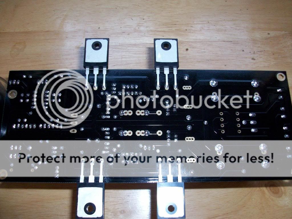
Good point, the board being supported at each end and with the weight of those heavy supply caps means it could flex a bit if badly handled by a courier.
I was going to re-use an enclosure which I already have a JC-2 clone fitted in but I think I will buy a new one for this build, even though it might take me a bit longer to complete because of it, it will be worth the wait.
I would also like to take this opportunity to thank Mike (tea-bag) for his kind help in supplying me with most of the components needed. This is a great forum with some great members. Cheers folks!
Davy
I wish that I had my consultation before ordering 12V toroidVery nice pictures. Confirm at least 15VDC on each polarity big filter capacitor with your Tx and mains combination at the times of day you usually sit for critical listening.
 on last few days my mains drop every 10minutes and my fluorescene lamp flickers and I can hear "ttzzz" during Vdrop on my gainclone
 My friend use the same heatsink and he built SK82 sit @2A and he said that the heatsink just a bit warm,so I copy his layout. I also can not find better option to make standard vertical mountNice heatsinks but their efficiency is severely reduced by mounting them horizontally.
I'll take 200mA option if I get lower Vout as should be. What is your audio source? Since I still use souncard output from my old thinkpad X61If you remember I took mine back down to 200mA as I couldn't hear any difference.
not expecting too much now. build a new dac is my next projectI wish that I had my consultation before ordering 12V toroid
An externally hosted image should be here but it was not working when we last tested it.
Don't they make any locally or in Philippines? One such unit it could feed steady AC the whole audio system and then some more.
Years ago I've used a local stavol, they copy exactly the same front panel and naming, 1kva only $30. But it burned some of my equipments, pfuff and smoke
Years ago I've used a local stavol, they copy exactly the same front panel and naming, 1kva only $30. But it burned some of my equipments, pfuff and smoke

I'm going to build DCB1 with a custom board and I have a some questions:
Planning about 200mA and 10Ohm as suggested by many.
The question is that 10/5W is advised. Is it good with 1 wire resistor or I should use more smaller (2/3W) metal resistors? I also simulated the circuit and saw that with 200mA, there is about 0,5W heat generated. Is 10/5W res necessary?
About the leds. I couldn't find 1.8V leds near me. I found 1.75V and 1.9V types. Which is better?
Also there is the 1Ohm resistor. In another setup it is 10Ohm. How much should it be?
I will use 50VA 2x12V toroid trafo.
Last edited:
What do you mean a "custom board"? You designed & etched it yourself at home?
You can use a single 10R or make the value from multiples but make sure the result is 2W+
and there is clearance for air to circulate under and above it.
0.5W constant power pushes a resistor thermally and needs to be chosen in over spec.
5W is usually the "small" type in some quality wirewound non inductive makes, that is why its specified. It also gives room to further "hot-rod" smaller value choices.
Use 1.9V LEDS. Use a jumper instead of that 1/10R test point resistor which is located towards ground.
Hi, I got my DCB1 black up and running, still only warm after an hour so that's ok.
Voltages as follows.
+ rail = plus 10.36v
- rail = minus 10.24v
R out = minus 02.8 (1000mv range)
L out = minus 01.4 (1000mv range)
Should one of the outputs not be plus volts?
Cheers
Davy
Voltages as follows.
+ rail = plus 10.36v
- rail = minus 10.24v
R out = minus 02.8 (1000mv range)
L out = minus 01.4 (1000mv range)
Should one of the outputs not be plus volts?
Cheers
Davy
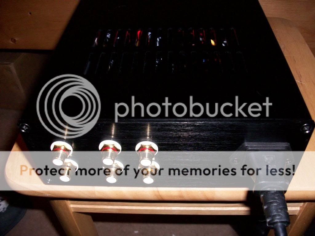
Thanks Salas, that's what I like to hear. I was going to buy a new enclosure but I have made a decent job of re-using one I bought a few months ago so I just need to connect it up to the phono sockets, play some music through it and all being well, i'm done.
I will try to take some pictures of it finished. I already took some of the board earlier but it's dark now. Any interest in seeing them?
I will try to take some pictures of it finished. I already took some of the board earlier but it's dark now. Any interest in seeing them?
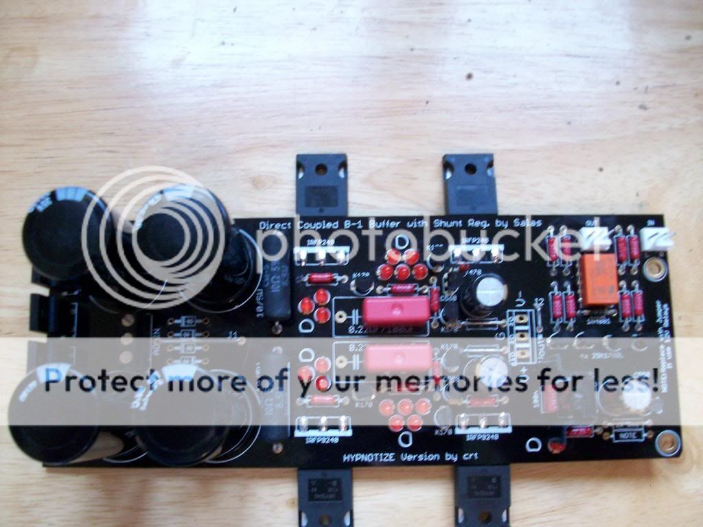
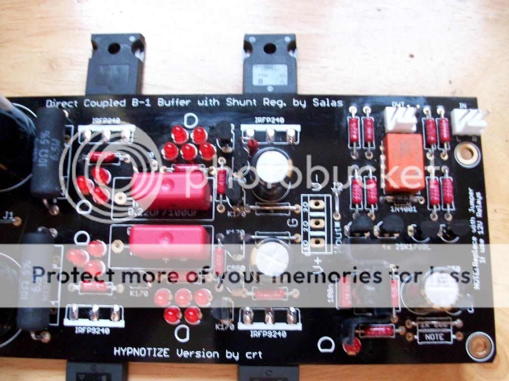
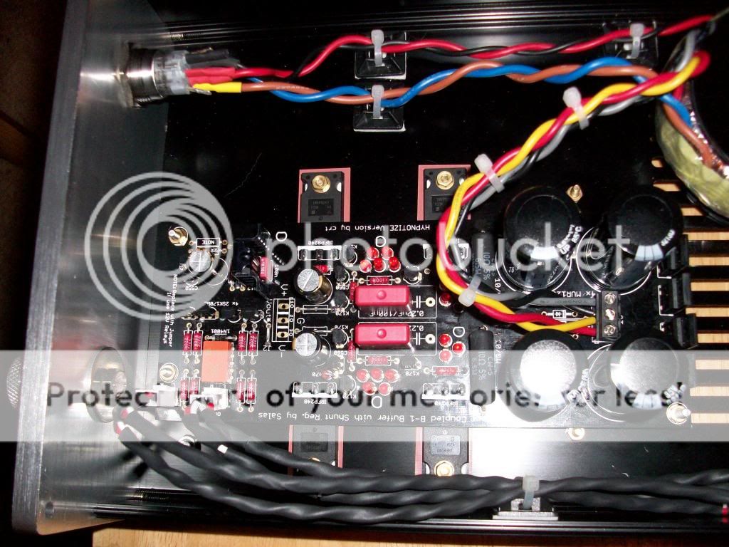
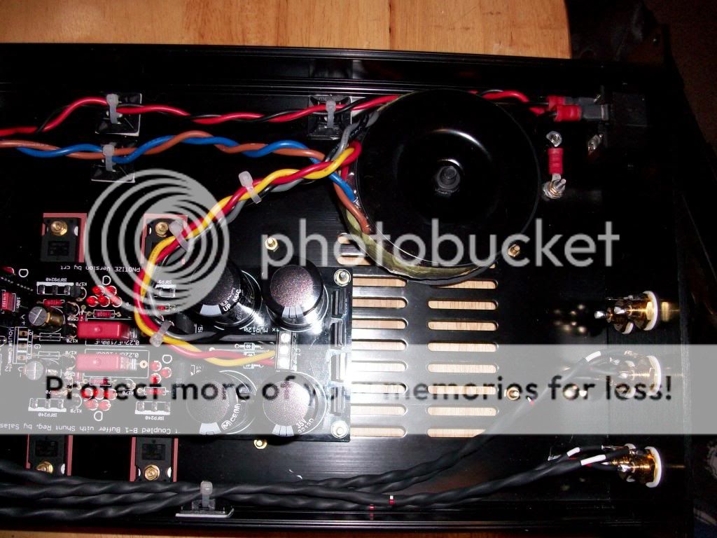
Some pictures of my DCB1 Black build. This was an easy build with an excellant quality board. First impressions are very good, it's open, transparent, dynamic and very quiet. Thanks to everyone involved
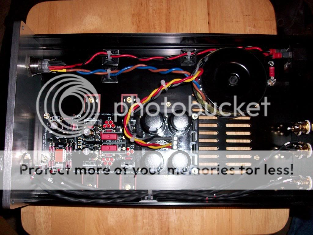
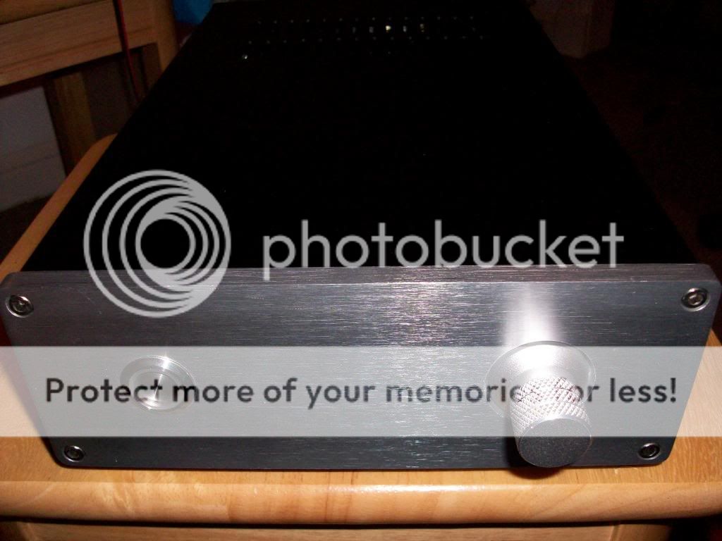
Keen eyed among you may notice my snake oil attenuator on the front pannel. This realigns the flux capacitor for improved interaction with the improbability drive.
Either that or it fills the blank hole where a pot should be, you decide


Keen eyed among you may notice my snake oil attenuator on the front pannel. This realigns the flux capacitor for improved interaction with the improbability drive.
Either that or it fills the blank hole where a pot should be, you decide
Last edited:
Is the power switch 12V? I think I have the same light and I run it from a pair of wire ran to the + and NEUT of the last LED here

I've ran my switch here for months with no issue or heat
If you go back to page 284 and 285 you will see some talk on this topic.. Nice build! where did you get that box?
I've ran my switch here for months with no issue or heat
If you go back to page 284 and 285 you will see some talk on this topic.. Nice build! where did you get that box?
Last edited:
Keen eyed among you may notice my snake oil attenuator on the front pannel. This realigns the flux capacitor for improved interaction with the improbability drive.
Either that or it fills the blank hole where a pot should be, you decide
Great job davym, thanks for pics. I´m still waiting for my kit. Well, what style of pot did you use to evaluate it??
- Home
- Source & Line
- Analog Line Level
- Salas hotrodded blue DCB1 build