I discover this just now: ")
http://www.diyaudio.com/forums/soli...w-distortion-lateral-mosfet-amplifier-12.html
And you use a much better circuit, in that one, congratulations.
You should upgrade this headphone amplifiers with the ideas you use in the lateral fet amplifiers.
http://www.diyaudio.com/forums/soli...w-distortion-lateral-mosfet-amplifier-12.html
And you use a much better circuit, in that one, congratulations.
You should upgrade this headphone amplifiers with the ideas you use in the lateral fet amplifiers.
Hi Sérgio, and thank you very much for your interest in my projects,
I used that current sources to have more output excursion, but I'm think now about using feedback current sources, because feedback current sources have a Ro of 1-2 Mohm which is much better when compared to the 200-300 kohm of the current mirror based current source.
Yes, you're right, I'm taking some ideas to this headphone amp in my experience with my higher power lateral MOSFET amplifier project. I will try to improve this circuit and I will post the pictures, maybe tomorrow or monday night.
Best regards,
Daniel
Ok, it makes sense
What you need is another power supply, I have some transformers with plus and minus 10V , 100VA with electrostatic shield , that can be good for a +9v,-9v power supply , as we live in the same city, I can offer you one, for you to use in your project.
You can also increase the output current for biasing in class A.
Hi everyone,
I've made some improvements to my design and I've converted it to dual supplies, what do you think?
I'm thinking about adding a simple VI limiter to the circuit, what do you think?
TDA7056 is a mono amplifier, you have to use two of them, pay attention because 3Wrms can be too much for the headphones, I've never tested that amp.
For headphones I've only tested TDA2822M which has good sound and it's very simple to mount. 2*LM386 it's another option, or one LA4525.
Best regards,
Daniel
Attachments
Hi smms73 and thank you for your concern,
Yes the capacitor C2 should be connected to Vcc, but for signal purposes it doesn't matter because Vcc and GND are constant voltage supplies (theoretically speaking of course, in reality there are ripple in Vcc and Vee, at 100 Hz because of the full wave rectifier).
I'm curious to see your different output stage, this one seems a little difficult to stabilize I've to add large base stopper resistors, otherwise I have peakings after the -3dB rolloff, in the other amplifiers I've never seen that happening.
Best regards,
Daniel
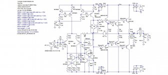
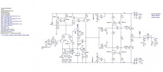
Daniel when C2 is connected to ground the +PSRR is 80db, if you connected to Vcc the +PSRR is 120db. The -PSRR is only 72db.
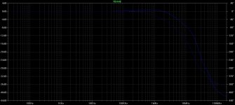
I have change the filter that you use for a simple capacitor multiplier, now the +PSRR is 140db and -PSRR is 120db at 100Hz.
The output stage is a diamond buffer, one good thing is that the maximum output current is limited in a case of short circuit at output, in this case a litle more than 500mA.
The output quiescent current is set by R30, in this case is 40mA.
I have also add c9 and R31 at the compensation net, to improve the phase margin.
Attachments
Last edited:
Hi Sérgio,
thank you very much for your help,
Why do you added Q15 and Q18 to the supply rails of the TCS/TIS, to improve power supply regulation?
The capacitors at the base of this transistors really have to be so high? Why the drivers don't have base stopper resistors?
I don't know that type of compensation. How it's called?
Why do you removed the helper transistor at the TCS current mirror?
Why do you use a 250ohm test load?
How do you perform the PSRR analysis?
Sorry for making all those questions,
Best regards,
Daniel
q15 and q18 are call capacitor multiplier, google it and you will have a lot of information, in this case I use them to improve the PSRR of your amplifier. 470uf is not that hight.
The drivers do not need base resistors.
I do not know how the compensation is called, You can call it 3 pole compensation if you want, I have discovered this litle trick some years ago when I first start to study 2 pole compensation.
I realy dont think that is need a more complex current mirror at the input, in reality the added complexity can be worst.
The 250 ohms is the impedance of my headphones, you can use other impedance, dont forget the amplifier start to cut at 500ma out, lower the value of R30 if you need more current out.
to perform a PSRR analyses you need to make one of the power supply voltage source the "AC 1" , and do a AC analyses, and then measure at the output. If you have doubts about this , please ask again, and I will explain better tomorrow.
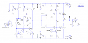
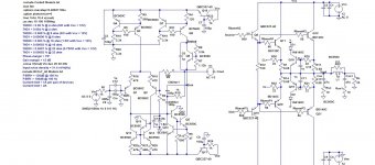
this is the same circuit but ready for PSRR analysis, just measure the output.
Ps: look what I did at Vcc for +PSRR, for -PSRR make Vee "AC 1" and erase "AC 1" from Vcc , try to erase the capacitor multipliers, and see how the PSRR change.
Ps: look what I did at Vcc for +PSRR, for -PSRR make Vee "AC 1" and erase "AC 1" from Vcc , try to erase the capacitor multipliers, and see how the PSRR change.
Attachments
Last edited:
Hi Sérgio and thank you very much for your great help
What can be considered a good PSRR value?
Two pole compensation and TMC are bad?
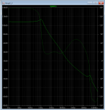
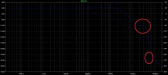
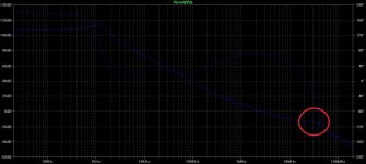
I think you are wrong, without base stopper resistors at the drivers you have a large peaking, a pair of poles that cause the peaking and that can be a local instability, when I added the resistors the peak disappered (attached pictures of the open loop gain).
The improved current mirror is good it improves distortion characteristics and provide lower offset at the output because it loads the TCS symetrically because as you can see both outputs of the VAS have a transistor of the same model and with the same configuration.
The values for the 3 pole compensation are made by experimentation, or I should follow some rule?
Best regards,
Daniel
What can be considered a good PSRR value?
Two pole compensation and TMC are bad?
I think you are wrong, without base stopper resistors at the drivers you have a large peaking, a pair of poles that cause the peaking and that can be a local instability, when I added the resistors the peak disappered (attached pictures of the open loop gain).
The improved current mirror is good it improves distortion characteristics and provide lower offset at the output because it loads the TCS symetrically because as you can see both outputs of the VAS have a transistor of the same model and with the same configuration.
The values for the 3 pole compensation are made by experimentation, or I should follow some rule?
Best regards,
Daniel
Attachments

Last edited:
Hi everyone,
I've made some changes to the circuit you've suggested, as I said previously I've added base stopper resistors at the drivers. I've also improved my previous design, I've increased the PSRR, using the capacitor multipliers like you've suggested, I've changed the compensation capacitors values to have a little more phase/gain margin and I've also added a current limiter circuit that seems to work very well. I like your diamond drivers idea, but I want to make something more simple, like the simple EF I'm using.
I also don't know if I want to use the 3 pole compensation method, I like simple 2 pole TMC. The 3 pole compensation add a little more phase margin, but doesn't show a significant increase in reducing THD/ raising the slew rate.
Thank you very much for your great help Sérgio,
Best regards,
Daniel
Attachments
Last edited:
Hi Sérgio and thank you very much for your great help
What can be considered a good PSRR value?
Two pole compensation and TMC are bad?
I think you are wrong, without base stopper resistors at the drivers you have a large peaking, a pair of poles that cause the peaking and that can be a local instability, when I added the resistors the peak disappered (attached pictures of the open loop gain).
The improved current mirror is good it improves distortion characteristics and provide lower offset at the output because it loads the TCS symetrically because as you can see both outputs of the VAS have a transistor of the same model and with the same configuration.
The values for the 3 pole compensation are made by experimentation, or I should follow some rule?
Best regards,
Daniel
Daniel, a good PSRR for me is better than 100db minimum.
Two pole compensation are fine (I dont know what TMC means).
But nowadays I prefer no poles at all
The problem of the gain peaking is not caused by the base stop resistors, but by the way you do the compensation, I normaly do like this ( calculate the miller capacitor, then add a capacitor with 10X the miller cap value, and then add a resistor betwwen 1k and 10k to ground) , connecting the compensation net to the output creates instability, expecially in a power amplifier connected to speakers.
I have test the distortion with your type of mirror and with a normal type at 20Khz/32Rout , and the results are 0.00052% with and 0.00053 without, In a real circuit will be even less as in spice the transistors are equal , in real life they are not.
Later I will post the circuit modifications for better stability. I try to post it but it give an error.
Hi Sérgio thank you for your help,
TMC (Transitional Miller Compensation) is a variant of two pole compensation and it's used to achieve higher slew rates at lower frequencies (like the audio frequencies), it is a form of compensation proposed by Cherry and modified by Peter Baxandall, it's called transitional because for lower frequencies the impedance of the 2nd capacitor is higher in it's absolute value when compared to the impedance of the resistor, for higher frequencies the second capacitor has a impedance lower than the resistor in module and the compensation network begins to act like common Miller compensation scheme, the peaking is caused by a pair of complex poles at the output EFs, with simple Miller compensation it appears too. TMC is not unstable see the threads of my MOSFET amplifier and the Honey Badger by Peter V (ostripper) or you can consult Bob Cordell's book, chapter 9 (Advanced forms of Compensation), page 182.
All amplifiers have at least one pole, caused by the internal parasitic capacitances (because of the depletion regions), otherwise the amplifiers will have infinite bandwidth.
The compensation you're suggesting me to use is lag compensation?
PS:
LM741 uses an improved current mirror, TDA2822M and LM4766 use a compensation network that includes the output (IMC - Inclusive Miller Compensation), and as I said the Honey Badger has a TMC compensation scheme as many other actual solid state amplifies.
Best regards,
Daniel
The problem of the gain peaking is not caused by the base stop resistors, but by the way you do the compensation, I normaly do like this ( calculate the miller capacitor, then add a capacitor with 10X the miller cap value, and then add a resistor betwwen 1k and 10k to ground) , connecting the compensation net to the output creates instability, expecially in a power amplifier connected to speakers.
TMC (Transitional Miller Compensation) is a variant of two pole compensation and it's used to achieve higher slew rates at lower frequencies (like the audio frequencies), it is a form of compensation proposed by Cherry and modified by Peter Baxandall, it's called transitional because for lower frequencies the impedance of the 2nd capacitor is higher in it's absolute value when compared to the impedance of the resistor, for higher frequencies the second capacitor has a impedance lower than the resistor in module and the compensation network begins to act like common Miller compensation scheme, the peaking is caused by a pair of complex poles at the output EFs, with simple Miller compensation it appears too. TMC is not unstable see the threads of my MOSFET amplifier and the Honey Badger by Peter V (ostripper) or you can consult Bob Cordell's book, chapter 9 (Advanced forms of Compensation), page 182.
But nowadays I prefer no poles at all
All amplifiers have at least one pole, caused by the internal parasitic capacitances (because of the depletion regions), otherwise the amplifiers will have infinite bandwidth.
The compensation you're suggesting me to use is lag compensation?
PS:
LM741 uses an improved current mirror, TDA2822M and LM4766 use a compensation network that includes the output (IMC - Inclusive Miller Compensation), and as I said the Honey Badger has a TMC compensation scheme as many other actual solid state amplifies.
Best regards,
Daniel
I can not post Attachments, maybe an error in diyaudio, will try to post the circuit tomorrow.
See,
http://www.diyaudio.com/forums/forum-problems/244247-problem-posting-pics.html
- Status
- This old topic is closed. If you want to reopen this topic, contact a moderator using the "Report Post" button.
- Home
- Amplifiers
- Headphone Systems
- Simple Headphone's Amp for beginner