I make my own film caps using cat 6 or kynar insulated wrapping wire as twisted pairs when I want values less that 10pF. Getting down to 1pF is doable but 1aF ( or whatever it was ) would be quite a challenge.
I guess if anyone has made values like that someone on this thread would know about it.
come on - amaze me")
I attofarad..a thousandth of a femptofarad, a millionth of a picofarad.
Hmm. I guess if you polished the end of two 30 guage wires, held them an inch or so apart???
Who in the world would need 1 attofarad??
jn
We expect that what you put up, Scott, is accurate without typos.'-) I did note that the rest of the component polarities seemed to be OK. What is it that you want to do with this topology? It IS an OP AMP, it is something that cannot be made with an IC process, as I understand it. Do you have any source available for this topology?
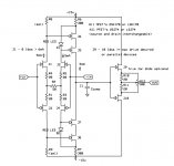
This is a quick example of a general purpose amplifier. The noise is 2-3nV (not particularly optimized) so at least it is better than other FET op-amps. Do red LED’s make noise? If so just sub a couple of 1N4148’s in series for each. There are other choices for the R1 – R5 network here the 20 Ohm resistors set the operating current and R2 help set the final gm of the input stage. R8 and R9 are selected or trimmed for current in J5 – J8. They also can be tweaked to null the offset reducing the need to match devices. As said elsewhere R6 and R7 are much larger than usual so that there is little or no voltage gain at R8 and R9 and the circuit acts more like just a gm and folded cascode to the gain node. Surprisingly the Aol can be several 100k’s even approaching 120dB from essentially one stage.
Ccomp is selected for stability depending on closed loop gain and of course one could play with using this amplifier open loop by loading the gain node with a network. You might want to increase the current in J5 – J8.
At least in simulation as a conventional op-amp at G = 100, 20kHz, 10 p-p into 2K the distortion is ~ -80dB. Under less stringent conditions it is much better. See how close JC is to making op-amp’s and using lots of feedback.
All in fun.
Attachments
I attofarad..a thousandth of a femptofarad, a millionth of a picofarad.
Hmm. I guess if you polished the end of two 30 guage wires, held them an inch or so apart???
Who in the world would need 1 attofarad??
jn
The MEMS guys mention zeptofarad's in some presentations.
Yeah, I once had a woman who talked like that. Also irrelevant
If all you do is play CDs then 100 db is enough. If you go to a 24 bit format you really will have 130 db of range available, so you just might want to use it. Eventually 24 bit may actually get to 140+ S/N.
That Grrrz feerkle blervic R.M. has got me thinking about how it is possible to actually measure well below -160 dB!
Right now I am finishing up a loudspeaker test chamber for the AES. It doesn't work! (You can't win them all.) However I have figured out how to make it work, I think. Is there really any DIY interest in an anechoic chamber .8 x 3.5 x 2.4 M ?
It occurs to me the mic preamp that was posted here a bit back might make an article, any interest?
zeptofarad
The fourth Marx Brother.
Scott, this IS the basic topology that we have been using at Parasound for the last 20 years, for both preamps and power amps, except with the later preamps, where we make it fully 4 quadrant differential. We can't live with 12V supplies, either.
Now is it the BEST topology? Well that depends. IF, you are making a line amp, it can be too much. It would be better to omit the complementary follower output stage and turn it into a Transconductance amp, or TA, just like the GD line drivers of 1973 that turned into the Levinson JC-2 line drivers that many like to make here.
However, IF, and there are a number of IF's, you need the services of a REAL op amp, with lots of open loop gain, + and - hi Z inputs, low open loop output, then this is an almost ideal topology to compete with IC's.
Zeptofarad effects in a 40/15000 Hz amp ?
Imho, dynamic / highest resolution / acoustic volume (electrical power) are not correlated : You need the three qualities altogether without loss of any or you loose illusion of reality ... Playing a CD on my triamped low efficiency system in a closed room, i surprised recently many accurate friends asking me : "Wow, you purchased a piano ?"
Imho, dynamic / highest resolution / acoustic volume (electrical power) are not correlated : You need the three qualities altogether without loss of any or you loose illusion of reality ... Playing a CD on my triamped low efficiency system in a closed room, i surprised recently many accurate friends asking me : "Wow, you purchased a piano ?"
The MEMS guys mention zeptofarad's in some presentations.
Their nuts..
There, that was easy...
Right now I am finishing up a loudspeaker test chamber for the AES. It doesn't work! (You can't win them all.) However I have figured out how to make it work, I think. Is there really any DIY interest in an anechoic chamber .8 x 3.5 x 2.4 M ?
How low was it supposed to go? The absorber lengths would exceed the cabinet by what, an order of magnitude at LF. Mids or tweets perhaps, but certainly not capable of absorbing bass anechoically.
The fourth Marx Brother.
You beat me to it..
jn
Zeptofarad effects in a 40/15000 Hz amp ?
Imho, dynamic / highest resolution / acoustic volume (electrical power) are not correlated : You need the three qualities altogether without loss of any or you loose illusion of reality ... Playing a CD on my triamped low efficiency system in a closed room, i surprised recently many accurate friends asking me : "Wow, you purchased a piano ?"
Of note is the fact that some of the original "op amps" had a folding over type pc board topology, where capacitance between elements played an important part. The opamp worked correctly when assembled, but not when unfolded.
Ya gotta wonder what level of capacitance they needed by proximity.
jn
That caused a small question mark, but hitsware's cct's I don't get at all - but that just might be me
Page Title
Zeptofarad effects in a 40/15000 Hz amp ?
I'll lay you 5 to 1 that it was put into the sim only, probably to help convergence.
How low was it supposed to go? The absorber lengths would exceed the cabinet by what, an order of magnitude at LF. Mids or tweets perhaps, but certainly not capable of absorbing bass anechoically.
jn
Yes bass! Before I tell you how, think about it.
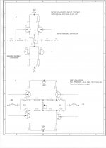
Now, let us look further into the all-jfet OP AMP schematic that Scott put up, and how could we 'improve' it. First we could make it QUIETER, by taking out the gain reducing structure of resistors and putting in a single resistor, instead.
Now for the output stage, we could put in a pair of complementary MOSFETS and get the voltage swing up by using +/- 18V supplies. To go up to +/- 30V supplies (ideal), we have to complementary cascode the input stage as well. There ARE higher voltage complementary jfets, as well that can be used as the second stage cascode devices, as well as mosfets. This is what we do to optimize the topology.
Sometimes we REMOVE the output buffer, and beef-up the second stage, keeping the original input stage for gain control.
Sometimes we keep the output buffer, BUT use complementary mosfets, instead of jfets.
Sometimes we go to 4 quadrant operation with fully balanced input and outputs.
Sometimes we use complementary mosfets as output followers and add a multiple complementary array of power bipolar transistors. (Almost all Parasound power amps uses this approach)
Sometimes we use the complementary folded cascode as the 'second stage'.
Charles Hansen likes to do this.
ETC
There is NO ONE SPECIFIC CONFIGURATION that is best for this topology it depends on what it is designed to do.
If all you do is play CDs then 100 db is enough.
I have at least one totally (I think) uncompressed 44.1/16 CD that I find unlistenable under normal (even fairly quiet) conditions. To tolerate the loud parts the quiet parts require you to put your head up to the speaker. Or listen like they do at audiophile shows and drive everyone else away.
Sometimes we use complementary mosfets as output followers and add a multiple complementary array of power bipolar transistors.
Thanks for this input John.
Could you clarify the above ?
Do you mean composite mosfet / BJT darlington type configuration complementary followers ?
- Status
- Not open for further replies.
- Home
- Member Areas
- The Lounge
- John Curl's Blowtorch preamplifier part II