I didn't see any reference to the relationship between the resistor value and the spurs. I can understand resistor noise, but it's unclear to me how added noise (1/f?) at the input of the A/D causes harmonically related spurs to occur. An explanation or perhaps a reference/link/citation might be good to read.
So the next question is what is the relationship between the resistor value and the spurs? If we go down to say 1k, 100 ohms or 25ohms what is gained? It ought to be possible to build up a buffer that can drive 25 ohms and still maintain sufficiently low distortion...
Perhaps applying the bias at the output might be advantageous? Like the old class A opamp pull up?
_-_-
It's not the resistors noise it's the noise radiated onto the resistor. A small current in a large value resistor will generate a larger potential across the resistor than a low value resistor. Basic ohms law. Noise from all the digital going on about the ADC can get in this way.
I didn't see any reference to the relationship between the resistor value and the spurs. I can understand resistor noise, but it's unclear to me how added noise (1/f?) at the input of the A/D causes harmonically related spurs to occur. An explanation or perhaps a reference/link/citation might be good to read.
So the next question is what is the relationship between the resistor value and the spurs? If we go down to say 1k, 100 ohms or 25ohms what is gained? It ought to be possible to build up a buffer that can drive 25 ohms and still maintain sufficiently low distortion...
Perhaps applying the bias at the output might be advantageous? Like the old class A opamp pull up?
_-_-
Bear I can't point you directly to a specific reference. I've done a tone of research on the industrial ADC side of things. You will get much more in depth information there than from any of the audio ADC literature. In audio the manufactures just say do it this way and leave it at that. The competition is so great you won't even get a look at the basic inner.
This is simply not the case with industrial ADCs.
Note that the Johnson noise (thermal noise) of a 1k resistor is about 4nV/rt Hz, and that the noise goes as the square root of resistance. So a 10 ohm resistor will be on the order of 0.4nV/rt Hz and a 100k resistor will be about 40nV/rt Hz.
Cheers,
Bob
Wonder what the output Z of the oscillator section might be. Without having looked QA might spec it. But if the output Z is low enough then I'd grab an appropriate resistor to parallel with the internal 100kohm on one channel and then compare the rise of the spurs before and after. Unfortunately, L & R channels don't exactly correspond so a direct comparison may not be good enough.
Wonder what the output Z of the oscillator section might be. Without having looked QA might spec it. But if the output Z is low enough then I'd grab an appropriate resistor to parallel with the internal 100kohm on one channel and then compare the rise of the spurs before and after. Unfortunately, L & R channels don't exactly correspond so a direct comparison may not be good enough.
The output Z is 68 ohms.
I think the issue is that current is drawn from the reference at the comparison time. This is similar to the bit of charge transferred by a sample and hold. The small bit of current can cause a small shift of the reference which if synchronous with the input will generate harmonics. I would not be surprised if the inputs to the ADC act similarly. It would not take much to degrade the signal. Remember these are all 120 dB down (1 PPM) so even a little impedance/current fluctuation will cause issues.
Hi Demian,
Sorry, I can't remember. Since the version number is not visible, it could be a rev. 1 or one of the pre-releases.
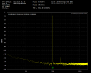
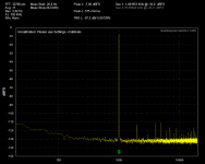
Anyway, there seem to be something going on here I don't understand. I just made these 2 plots. The only difference being that the first and "cleanest" one was taken with the QA400 just powered up and SW just started. The second one is taken after fidling a littlebit with the settings and a trail run at 48 KHz. But, as you can see I have restored the settings to be exactly the same as the ones used for the first plot. I can't understand the inconsistancy. I have seen this behavior with all the SW versions. But, I have never been able to figure out exactly what causes it, but changing sample frequency seems to be able to provoke it. As a SW guy my stomach feeling would be to start verifying the generator path. I think this must be a SW issue.
Mogens
MKC- That's really good. I would not trust it to give you the same plot again. At 192KHz sampling I don't get anything that good. Which version of the software are you using?
Sorry, I can't remember. Since the version number is not visible, it could be a rev. 1 or one of the pre-releases.
Anyway, there seem to be something going on here I don't understand. I just made these 2 plots. The only difference being that the first and "cleanest" one was taken with the QA400 just powered up and SW just started. The second one is taken after fidling a littlebit with the settings and a trail run at 48 KHz. But, as you can see I have restored the settings to be exactly the same as the ones used for the first plot. I can't understand the inconsistancy. I have seen this behavior with all the SW versions. But, I have never been able to figure out exactly what causes it, but changing sample frequency seems to be able to provoke it. As a SW guy my stomach feeling would be to start verifying the generator path. I think this must be a SW issue.
Mogens
Attachments
Last edited:
Hi Demian,
But, as you can see I have restored the settings to be exactly the same as the ones used for the first plot. I can't understand the inconsistancy. I have seen this behavior with all the SW versions. But, I have never been able to figure out exactly what causes it, but changing sample frequency seems to be able to provoke it. As a SW guy my stomach feeling would be to start verifying the generator path. I think this must be a SW issue.
Mogens
")
Does it happen when using an external generator source.
The first plot shows 192 KHz as the sample rate but the measurement noise floor only happens at 48 KHz sampling. I missed that detail at first. Its a software bug of some sort I think.
Set the system to 48 KHz, take a measurement. Shut it down and restart the app. See if it changes at all. Do the same with 192.
Set the system to 48 KHz, take a measurement. Shut it down and restart the app. See if it changes at all. Do the same with 192.
I think the issue is that current is drawn from the reference at the comparison time. This is similar to the bit of charge transferred by a sample and hold. The small bit of current can cause a small shift of the reference which if synchronous with the input will generate harmonics. I would not be surprised if the inputs to the ADC act similarly. It would not take much to degrade the signal. Remember these are all 120 dB down (1 PPM) so even a little impedance/current fluctuation will cause issues.
Sounds like what is needed is a time constant associated with the buffering opamp?
The AK schematic seems to show that the bias voltage they suggest is just a simple divider off the main supply. Or am confused on this?
Has anyone check the generator on another analyzer like the 725 or Panasonic.
There is a single tone option under 'Options'. Otherwise this is a sine pulsed generator and I don't trust it.
I neglected/forgot/ran out of time & didn't think of it last time. I will try to remember to look at the oscillator on Sunday, assuming the rest of the world cooperates (not likely).
Also need to make mental note to look at the option thingie for the oscillator too...
Anyone going to tack in a resistor and see what happens? Don't think that will release any smoke.
Its difficult because the generator runs in burst mode. Maybe in cal mode it could be checked.
Matt added in at my request an option to output a continuous tone. It's under 'Settings/'Generator fixed tone'.
The analyzer won't run but you can test the generator this way.
I did mean for the analyzer to run as well but it didn't go that way.
Last edited:
Sounds like what is needed is a time constant associated with the buffering opamp?
The AK schematic seems to show that the bias voltage they suggest is just a simple divider off the main supply. Or am confused on this?
There is a TC. The low pass filtering of the driver provides this.
You are right about the bias voltage. The VCOM provides this but it's not absolutely necessary.
The VCOM filtering is essential for a flat noise floor. Crystal states not more than 1uF here and for good reason. Matt and I experimented with this during beta testing. The noise floor will improve with a larger cap value but it won't be flat.
VCOM is the reference voltage for the ADC.
I'll see if I can dig up the old emails with screen shots.
VCOM is the reference voltage for the ADC.
I'll see if I can dig up the old emails with screen shots.
Please excuse my lack of prior knowledge on this.
Is not the VCOM voltage internally generated in the ADC?
So, it is an internal reference voltage brought out to a pin??
As far as not flat noise floor, I'm not so interested in that as much as getting the spurs out of the display when the fundamental is near 0dBfs. Although the noise floor is interesting.
Demian, if I understood, seemed to say that VCOM "pumped" in harmony with the input signal as the result of the way the ADC operates internally to generate the voltage at VCOM??
Please excuse my lack of prior knowledge on this.
Is not the VCOM voltage internally generated in the ADC?
So, it is an internal reference voltage brought out to a pin??
As far as not flat noise floor, I'm not so interested in that as much as getting the spurs out of the display when the fundamental is near 0dBfs. Although the noise floor is interesting.
Demian, if I understood, seemed to say that VCOM "pumped" in harmony with the input signal as the result of the way the ADC operates internally to generate the voltage at VCOM??
Bear the ADC loads the input during a conversion which in turn loads the driving circuit. This can cause noise during conversion which is mixed with the signal and can generate spurs. If Crystal is using switched capacitor technology at the input then this very likely a cause.
- Home
- Design & Build
- Equipment & Tools
- QuantAsylum QA400 and QA401