What is the preferred front-end (voltage gain stage) for a single-ended F4?
I am looking at the BA3 FE, Pumpkin, Blowtorch, and various opamps. The difficulty is getting enough voltage swing and a voltage gain of 6x or better with low distortion, particularly higher order harmonics.
I am looking at the BA3 FE, Pumpkin, Blowtorch, and various opamps. The difficulty is getting enough voltage swing and a voltage gain of 6x or better with low distortion, particularly higher order harmonics.
I would say BA3(actually BA3B) based on our conversations. I would tend to lean towards Pumpkin personally, but the BA3B may come close to the sonic signature I would expect from Pumpkin, at least closer than other PP FE's. Pumpkin is a beast and Generg has had nothing but positive things to say. In other words. You cant lose.
buzz, you beat me to it
Me, ditto.
I think Generg prefers the Pumpkin and 'crippled' F4 even more.
I would have thought the BA2 would be closer to a 'single ended' input and output Pumpkin.
I would tend to lean towards Pumpkin personally......... .........Pumpkin is a beast and Generg has had nothing but positive things to say.
Me, ditto.
I think Generg prefers the Pumpkin and 'crippled' F4 even more.
.......the BA3B may come close to the sonic signature I would expect from Pumpkin, at least closer than other PP FE's.
I would have thought the BA2 would be closer to a 'single ended' input and output Pumpkin.
Just had another look at the BA3B, I didn't see any current feedback.
If you remove the left output of the Pumpkin and ground the right input via a capacitor, then flip the circuit top to bottom, Ok it is cascoded and has a current sink in the output stage (or is that current source since the flip lol) but other than that, it does look similar to a BA2.
If you remove the left output of the Pumpkin and ground the right input via a capacitor, then flip the circuit top to bottom, Ok it is cascoded and has a current sink in the output stage (or is that current source since the flip lol) but other than that, it does look similar to a BA2.
If driving a single-ended F4, why would one use a balanced BA3 FE rather than unbalanced?
You would do this when you have for instance a CD -Player with balanced Output.
With the balanced BA-3 you have a kind of UGS6 and it is open to all kinds of in and outputs.
PumpKING and F4 was a very very God combination......

And it offers the same variations of in and outputs, but I did not compare BBA-3 and Pumpkin under the same conditions......
Just had another look at the BA3B, I didn't see any current feedback.
If you remove the left output of the Pumpkin and ground the right input via a capacitor, then flip the circuit top to bottom, Ok it is cascoded and has a current sink in the output stage (or is that current source since the flip lol) but other than that, it does look similar to a BA2.
Your are correct, but with slight adjustment it it possible. For now they just exchange current info through source connection of input pair.
I just completed building a BA-3 and want to connect it to a crippled F4 I am in the process of building. I am not at all sure how to do this.
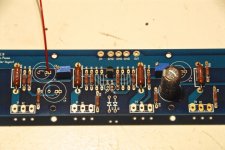
Attached is a picture of my crippled F4. Is it correct/complete (mosfets will be added, of course)? It certainly looks crippled to me.
To connect the BA-3, do I jumper C2 and connect BA-3's output to C2+ as shown?
Sorry for the basic question!
Attached is a picture of my crippled F4. Is it correct/complete (mosfets will be added, of course)? It certainly looks crippled to me.
To connect the BA-3, do I jumper C2 and connect BA-3's output to C2+ as shown?
Sorry for the basic question!
Attachments
Last edited:
Has anyone built a Blowtorch based front-end for the F4? The main difficulty is getting the voltage swing up to 20V peak, requiring fairly high rail voltages and not only the folded cascode devices but probably also cascoding of the input JFETs in order to reduce power dissipation on the JFETs. The Blowtorch wasn't designed for an output voltage swing of +/-20V on each output.
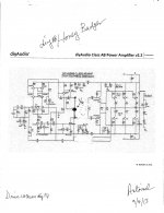
lhquam. The attached schematic is that of a modified diyAB "Honey Badger". It is a general illustration on how to obtain a high output Vo; so as to easily drive your diyF4. First discard the bias regulator and the output stage in its entirety. Then connect together the collector leads of Q10, Q12 and the start of the global feedback circuit as shown to get the output port.Has anyone built a Blowtorch based front-end for the F4? The main difficulty is getting the voltage swing up to 20V peak, requiring fairly high rail voltages and not only the folded cascode devices but probably also cascoding of the input JFETs in order to reduce power dissipation on the JFETs. The Blowtorch wasn't designed for an output voltage swing of +/-20V on each output.
Best regards.
Attachments
I am currently using a BA3FE with my F4 and it seems to work ok. I also have parts for an Impasse on order. But I am curious about how a low distortion, no global feedback, folded-cascode like the Blowtorch might sound with the F4.Why not use a Pumpkin, BA-3 or ImPasse?
The voltage mismatch across the 0.47r resistors won't be more than 6mv even with 1.5a bias so it would not seem to matter so much. It turns out also that in practice these particular resistors are much more closely matched to each other than the 5 pct tolerance would imply.
But if you have a few - why not
But if you have a few - why not
Last edited:
But if you have a few - why not
Thanks for your reply. No, I don't have any. Just starting my F4 project. I can buy 1% resistors, but they are more expensive. Question whether it is worth spending more money or not...
- Home
- Amplifiers
- Pass Labs
- F4 power amplifier