[snip]likewise the stated and by now "assumed correct" "official audiophile position" is that low/no feedback is "audibly superior" - but as far as I know this hypothesis hasn't been shown to be supported in controlled listening tests
It's rigged towards marketing. I know of two instances where a reviewer stated that "the amp sounded surprisingly well despite the low distortion" (my italics).
jan didden
I totally agree with what you're saying here (sorry, but I came into this thread rather late). Having spent 4 years earning a BSEE and many more years studying audio and music electronics, I find it very frustrating when designers try to deny that they are using feedback in their amplifier designs when the circuits in question most surely represent textbook "feedback."of course it helps when language Aids understanding
I could be fine with quote marks: "no feedback" being a purely Marketing term - it could also help to use the trademark symbol on that too
but as you can see from the discussion here it generates considerable cognitive dissonance in non-experts who (rightly, IMHO) feel betrayed by the marketing language that they likely 1st experience and internalized when they then have to deal with real feedback theory discussions
it seems wrong to argue against using language consistent with the engineering definitions - particularly in a diy forum where we hope "correct" circuit understanding could have some value to builders - or at least using the words to mean the same things could help their communication with formally trained EE circuit designers and in reading for self education
the informal language doesn't always have to put every important formal distinction in the way - but the word "feedback" shouldn't mean the opposite in the ad copy vs what engineers designing the circuit use (at least in textbooks, class rooms, IEEE peer reviewed papers... despite whatever Charles may actually think while using Blackman's formula to calculate input/output impedances)
It's almost impossible to discuss anything as technical as amplifier circuits when those who have products being reviewed by the audiophile press cannot use the same terms as trained engineers without fear of needing to defend their product because it might be seen as having that 'evil' feedback.
Effect of degeneration on distortion
[image][/image]Don't mean to disturb this thread's peace, but I wanted to document some interesting (to me) findings.
I had been under the impression (mistakenly as it turns out) that feedback applied through degeneration did not have the 'distortion spreading' effects of conventional feedback.
I did some sims on the denegeration version to find out.
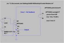
The first case looks like a follower but we can see that there is NO feedback applied and so we get gain.
Case 1 results
Id=620mA
Output Voltage = 5V pk-pk
Input voltage = 0.14 pk-pk
Gain is therefore = 35.7x [31db]
THD = 2.92% [-30.7db]
*******************
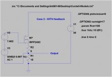
The second case uses all the same parts but now we have feedback from R2 as its included into the Vgs path. The current through the fet (Id) develops a voltage drop across R2 and so the bias voltage voltage source needs adjusting in order to keep Vgs and therefore Id identical to the no fb case.
The signal remains measured across R1 (same 15R load as before). Now that we have some fb, the gain drops quite a bit.
Case 2 results
Id= 620mA
Output Voltage = 5V pk-pk
Input voltage = 1.81V pk-pk
Gain is therefore = 2.76x [8.8db]
THD = 0.23% (-52.7db)
****************
So lets see. Gain has dropped by 22.2db from 31db to 8.8db.
And distortion ? Thats dropped a lot too. From -30.7db to -52.7 db.
Thats a 22db improvement in return for giving up the same amount of gain. Ok so thats a nice improvement and fits with what the books tell us ..... but what about the spectrum of the distortion ?
[image][/image]Don't mean to disturb this thread's peace, but I wanted to document some interesting (to me) findings.
I had been under the impression (mistakenly as it turns out) that feedback applied through degeneration did not have the 'distortion spreading' effects of conventional feedback.
I did some sims on the denegeration version to find out.
The first case looks like a follower but we can see that there is NO feedback applied and so we get gain.
Case 1 results
Id=620mA
Output Voltage = 5V pk-pk
Input voltage = 0.14 pk-pk
Gain is therefore = 35.7x [31db]
THD = 2.92% [-30.7db]
*******************
The second case uses all the same parts but now we have feedback from R2 as its included into the Vgs path. The current through the fet (Id) develops a voltage drop across R2 and so the bias voltage voltage source needs adjusting in order to keep Vgs and therefore Id identical to the no fb case.
The signal remains measured across R1 (same 15R load as before). Now that we have some fb, the gain drops quite a bit.
Case 2 results
Id= 620mA
Output Voltage = 5V pk-pk
Input voltage = 1.81V pk-pk
Gain is therefore = 2.76x [8.8db]
THD = 0.23% (-52.7db)
****************
So lets see. Gain has dropped by 22.2db from 31db to 8.8db.
And distortion ? Thats dropped a lot too. From -30.7db to -52.7 db.
Thats a 22db improvement in return for giving up the same amount of gain. Ok so thats a nice improvement and fits with what the books tell us ..... but what about the spectrum of the distortion ?
Attachments
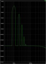
Turns out that the spectrum is also affected....
We can see the presence of higher order harmonics for the feedback case - even though the feedback is being provided through degeneration.
Something this obvious must be old news to many but frankly I was surprised (and a bit dissapointed) when I first saw it.
This does not mean that source degeneration is without virtue - it does make the application of NFB so very much simpler. Trying to apply these large amounts feedback across global loops (esp in multistage amps) would probably need fairly brutal compensation if it could be done at all.
I guess this could be one reason why follower output stages are the dominant type in commercial amps.
If anyone has any opinions on this, I'd love to hear them ....
Attachments
yes even degeneration gives "harmonic multiplication" - it is feedback after all
sometimes idealized cases can be clearer
Spice ideal Behavioral sources with "square law" equation and no feedback vs degeneration type feedback:
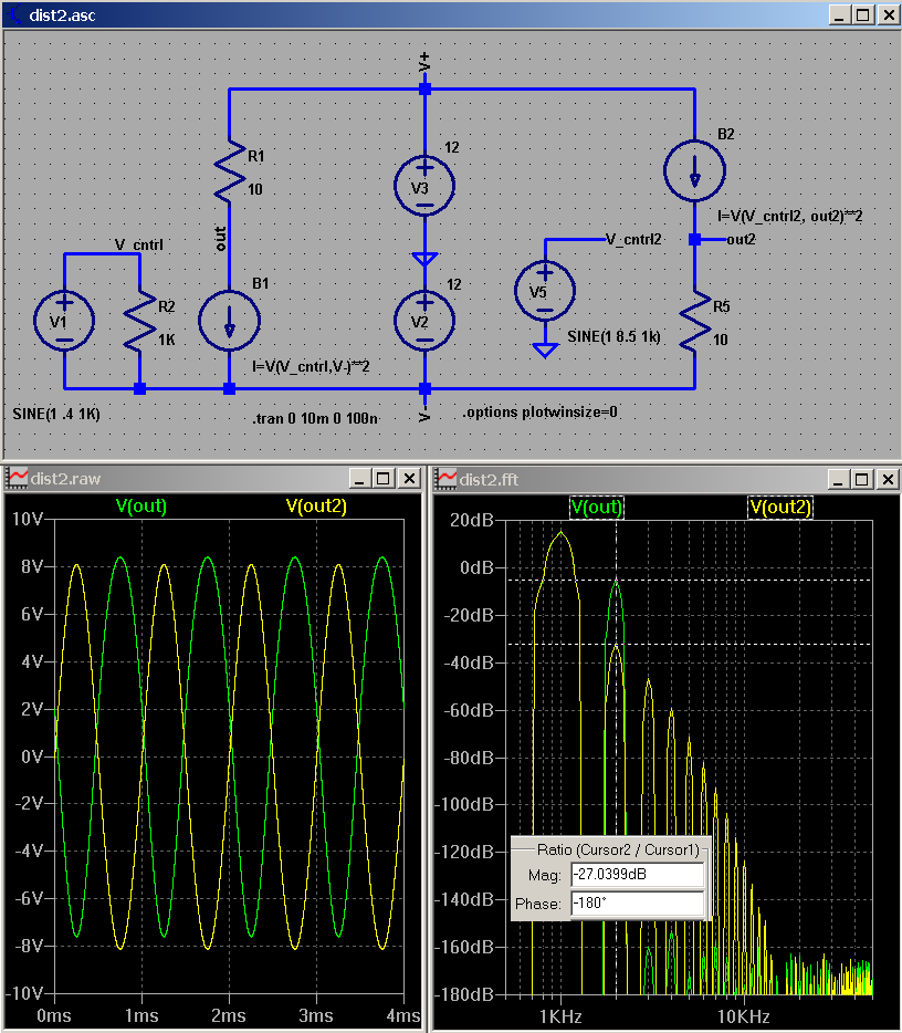
feedback around a square law device with only 2nd order open loop distortion gives all orders of harmonics in the feedback output - whether the feedback is local degeneration or not
sometimes idealized cases can be clearer
Spice ideal Behavioral sources with "square law" equation and no feedback vs degeneration type feedback:
feedback around a square law device with only 2nd order open loop distortion gives all orders of harmonics in the feedback output - whether the feedback is local degeneration or not
It look like that is true in this (limited) case.
The commercial and critical success of some no/lo global fb amps however, suggest that there is something allowed by degeneration that cannot be provided by loop feedback alone. At least not in a practical sense.
Be that as it may, the lack of harmonic 'smearing' does not appear to be one of these.
The commercial and critical success of some no/lo global fb amps however, suggest that there is something allowed by degeneration that cannot be provided by loop feedback alone. At least not in a practical sense.
Be that as it may, the lack of harmonic 'smearing' does not appear to be one of these.
Degeneration is local feedback. That means less problems with phase shifts than loop feedback, so more feedback can be applied without hitting stability or stage overload problems. Hence the apparent success of 'no feedback' amps almost certainly relies on large amounts of local feedback.
'No feedback' amps may also have a high output impedance (poor DF) which will lead to bass boom with most speakers. Some people prefer this sound.
'No feedback' amps may also have a high output impedance (poor DF) which will lead to bass boom with most speakers. Some people prefer this sound.
Some non-intuitive (to me) results from simulations.
In push-pull common source output stages,
adding degeneration reduces gain (expected) but increases distortion (err, what ??)
I tried this with both complementary (using cordells IRF240/9240C models) as well as with a circ output stage. The latter so that we can use perfectly identical parts. These are for the output stage only so that we can take a look at that in isolation.
So the conclusion seems to be that for push pull stages, it is better to use loop fb and avoid degeneration - if the rest of your circuit (incl phase shifts/stability) allows.
To me this seems at odds with accepted wisdom & so I'm not holding this out as irrefutable evidence but the results appear to point that way.
I'm inclined to think that I must be missing something - but if so, what is it ?
Take a look....
Attachments
Last edited:
FETs are not BJTs. They have a different in-out characteristic. Small amounts of degeneration do not provide enough feedback to guarantee distortion reduction; just enough to create distortion recycling.
The simplest example is the extra 3rd created by recycling a little 2nd back through the device. For a BJT (and a remote cutoff valve) this extra 3rd is antiphase with the inherent 3rd created by the device anyway - so a little degeneration will reduce 3rd by partial cancellation. For other devices (FET and 'straight' valves?) this extra 3rd is in phase with the inherent 3rd so it gets worse, until there is enough feedback to suppress distortion.
'Modest' amounts of feedback is often a bad idea. Either have none, or enough. In between you get problems.
Thanks - took a look. Doesn't appear to be due to the 'too-little-degeneration' effect.
Using the push-pull example above you can set the top fet to zero signal and just see the effect of a small increase in degeneration.
So the top fet just acts as a load to keep DC conditions similar.
Using this, we find that 0.47R degeneration reduces THD from 5.3% to 2.4% with corresponding reduction in gain. That is what I had found earlier up as well for larger amounts of degen.
So for single ended examples: degen=fall in gain= fall in distortion.
For push-pull: degen=fall in gain = RISE in distortion.
Last edited:
So for single ended examples: degen=fall in gain= fall in distortion.
For push-pull: degen=fall in gain = RISE in distortion.
I don't think you can generalise it like that, too many variables involved.
Have you tried to split R1 in two equals, mid point grounded?
I know it should make no difference but the distortion 'meter' is implicitly grounded.
jan
I did a little more work on this last night to see if the effect was maybe due to the small-ish output voltage used in the earlier sim.
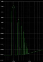
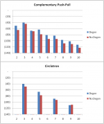
The results shown graphically below (floored at -140db.)
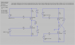
The circuit is the same as the one shown earlier, with just the o/p voltage increased to 30v peak to peak. The outcome appears to be the same at higher voltages.
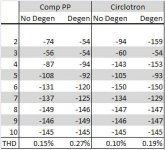
The circlotron case is shown also to demonstrate that the effects we are seeing are not due to mismatched N and P devices.
Both push-pull topologies show an increase in distortion when the op stage is degenerated.
For the complementary PP, THD went from 0.6% to 1% when subjected to 0.47R of source degeneration. For the circlotron, it went from 0.35% to 0.95%

The results shown graphically below (floored at -140db.)
The circuit is the same as the one shown earlier, with just the o/p voltage increased to 30v peak to peak. The outcome appears to be the same at higher voltages.
The circlotron case is shown also to demonstrate that the effects we are seeing are not due to mismatched N and P devices.
Both push-pull topologies show an increase in distortion when the op stage is degenerated.
For the complementary PP, THD went from 0.6% to 1% when subjected to 0.47R of source degeneration. For the circlotron, it went from 0.35% to 0.95%
Attachments
- Home
- Amplifiers
- Pass Labs
- Distortion and Negative Feedback