I can't think of an amplifier with RFI in the loudspeaker connections. What would the purpose be?
The feedback circuit.
Regards
M. Gregg
Well no, speaker cables along with power cables, control cables and interconnects make good RFI antennas. Once inside the chassis, the circuit looks very different to radio frequency RFI than to the audio frequency schematic printed in the manual.
Member Bob Cordell covers this in his big book 'Designing Audio Power Amplifiers'.
Jim Brown covers this in his paper:
A Ham's Guide to RFI, Ferrites, Baluns, and Audio Interfacing
Revision 5a 5 Jun 2010
by Jim Brown K9YC
Audio Systems Group, Inc.
http://www.audiosystemsgroup.com/RFI-Ham.pdf
Don't let the title fool you, this is just a new edition of a paper with aditional information for Ham's
***************************************
All unshielded multi-conductor cables should be twisted to reduce RFI pick-up.
***************************************
Shielded interconnects (balanced & unbalanced) depend on corrected mounted.connected chassis jacks to reduce RFI.
Last edited:
I have read of AM radio from nearby commercial transmitters being heard in speakers - with the amp power off
as often the longer wires (after the mains power wiring - in conduit?) in the stereo setup speaker cables may be of concern
EMI could couple differential and common mode
differential mode coupling may be reduced by twisting - but you have no control over what happens in the speaker - what are the XO air core inductor SRF?
clamp-on ferrites over speaker cable both strands together only affect common mode couping - and often only by single digit dB
http://www.elmac.co.uk/pdfs/ferrite.pdf
http://www.arvelo.net/N2MZZ/graphics/A Hamsguide-to-RFI-ferrrtes-baulns-audio-interfacing-k9yc.pdf - yes the same as above - it gets around...
I always thought that the Zobel and output choke were more about RFI than capacitive loads etc. or maybe it was just a side benefit. My new build will have both as I have an interference problem with my current system and want to get rid of it - it seems to be coming from a neighbouring apartment.
Brian
Brian
The first time I saw this issue mentioned was back in the early/mid 1970's when an update to the PW Texan amp was described. It included an RF rolloff filter in the feedback network, so RF picked up on the speaker leads would not cause the 741 opamps to get confused. It crops up again from time to time, but then seems to be ignored for a few years before reappearing. Maybe each new generation has to 'discover' it?
I'm listening to one right now! I own several others.I can't think of an amplifier with RFI in the loudspeaker connections.
(Class-D)
I once had a problem with RFI from the other side. My six meter transmissions were causing interference to someone's hi-fi. Never did solve it.
These days my speaker cables run near AC cords, computers, and SCR's but I don't have any interference problems that I know of. (There was a shortwave station in my phono stage that turned out to be caused by a Monster interconnect.)
Would there be audible benefit to adding ferrites all over everything? I'm sure there is a lot of RFI floating around here. But I don't think I can hear or taste or smell it.
I became a believer in ferrites when a company I worked for had to add ferrites on our products' cables to meet FCC certification.
I used to have a neighbor with a boosted-up CB radio. I'd be rudely awoken by his trucker voice blasting from my speakers every morning. (even if the stereo was off.) Ferrite,small bypass caps,shielded cables,different amps,more grounds,nothing fixed it. Luckily I wasn't the only one he annoyed,cause a couple weeks later they were gone,I suspect evicted.
I like the clip-on ferrite beads,and tend to use them a lot.Great for power cords,and other various cables. They're handy RFI stoppers,I at least kinda try to quench RFI/EMI,if I can.
(Trying to listen to a shortwave radio/scanner with a PC nearby is a mess of whistles,and 'ghost carriers',for example.)
I used to have a neighbor with a boosted-up CB radio. I'd be rudely awoken by his trucker voice blasting from my speakers every morning. (even if the stereo was off.) Ferrite,small bypass caps,shielded cables,different amps,more grounds,nothing fixed it. Luckily I wasn't the only one he annoyed,cause a couple weeks later they were gone,I suspect evicted.
One can be punished for that, at least in the US. The FCC would propose a non-technical solution.
Neville Thiele (of T/S fame) designed a LCR network for the output of a power amp' which, when connected to a speaker of appropriate impedance, increases amp' stability and also acts as an RFI filter for noise picked up by the speaker leads. I will try and describe it. Assume 8 ohms. There is a parallel LR network of 2mH and 8ohm in series with the output. Then instead of the classic 8R and small cap' in series from the hot (speaker end of the LC network) to the ground he just has a small cap'. About 0.1uF I recall. Looks odd but when the speaker is connected (i.e. across the cap') it forms an parallel RC network and all things being equal the amp then "sees" an 8 ohm resistance and any RFI picked up by the leads experiences a 6db/oct attenuation before getting to the output terminals.
The first version used on some local DIY magazine kits from the mid '70s was the basic version which gave a 6db/octave roll off. But if you chase up the JAES paper there are two further iterations of 2nd and 3rd order networks (more complicated and elegant) for very severe cases of interference. Can't think of the actual year and volume reference right now.............
actually it is; JAES 1976 24(1) pp 20-23.
Cheers,
Jonathan
Last edited:
I've found from experience that adding ferrites to a signal line is not to my tastes; it always seems to change the sound in a direction I don't like.
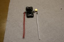
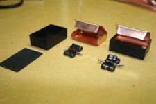
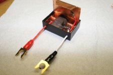
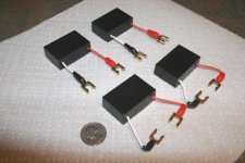
I did however, DIY some RC speaker cable filters that are still in place. Once installed at both the amp and speaker end of the wire they seemed to me to have a very positive effect on the sound. Whether they are filtering out RF or simply terminating the TL more effectively, I don't know, but they do something I like. I calculated the characteristic impedance of the speaker wires at RF and chose the resistor value to match that. The caps are cascaded silver micas. Before potting I embedded the caps in mortite to attempt to damp resonances. Inside the potting box is an inner box of TI-shield material.
Here are a few pics showing what I did. The final filters are potted in epoxy and as hard as bricks.
Attachments
- Status
- This old topic is closed. If you want to reopen this topic, contact a moderator using the "Report Post" button.
- Home
- General Interest
- Everything Else
- RFI and speaker cables?