Slight problem with power supply cradle height
As I have been working on my power supply and deciding on how best to wire things up, I noted a couple problems.
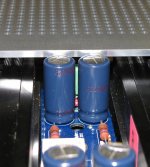
First, there are jumpers that I almost missed on the capacitor doubler boards under C2 and C22.
Second, with the 25mm tall 1000uf caps called out for C1,2,21,22 on the boards and using 10mm tall standoffs supporting the boards on the heatsinks, there is not enough clearance to close the top of the amps, even with the cradle in the down (float) position. It would not be possible to raise the cradle to the shipping position.
I looked at using a 5mm tall standoff for the board on the heatsink, but that puts the board right down on the mosfets and allows leads from other components to stick into the mosfets.
Another option was to shorten the vertical posts from the cradle to the heatsinks about 5mm. Certainly can do that, but might be tough for others with no metalworking equipment, taps, etc.
Another option obviously is using 20mm tall 1000uf 35v caps.
Digikey has the following 105 degree C caps:
493-1322-nd nichicon VZ 1000hr / 105 degree C. Ripple current 810mA
1189-1295-nd Rubycon YXJ 10,000hr / 105 degree C. Ripple current 1.43A
Panasonic caps are all 85 degree C in the 20mm height to fit the board.
I will likely go the easy route and get new caps, unless there is a compelling reason to stay with the Panasonic caps.
Matt
As I have been working on my power supply and deciding on how best to wire things up, I noted a couple problems.
First, there are jumpers that I almost missed on the capacitor doubler boards under C2 and C22.
Second, with the 25mm tall 1000uf caps called out for C1,2,21,22 on the boards and using 10mm tall standoffs supporting the boards on the heatsinks, there is not enough clearance to close the top of the amps, even with the cradle in the down (float) position. It would not be possible to raise the cradle to the shipping position.
I looked at using a 5mm tall standoff for the board on the heatsink, but that puts the board right down on the mosfets and allows leads from other components to stick into the mosfets.
Another option was to shorten the vertical posts from the cradle to the heatsinks about 5mm. Certainly can do that, but might be tough for others with no metalworking equipment, taps, etc.
Another option obviously is using 20mm tall 1000uf 35v caps.
Digikey has the following 105 degree C caps:
493-1322-nd nichicon VZ 1000hr / 105 degree C. Ripple current 810mA
1189-1295-nd Rubycon YXJ 10,000hr / 105 degree C. Ripple current 1.43A
Panasonic caps are all 85 degree C in the 20mm height to fit the board.
I will likely go the easy route and get new caps, unless there is a compelling reason to stay with the Panasonic caps.
Matt
Lets start with listening tests, I left the bias in 1.5A (2A is not practicable here in summer) (Also my speakers are 8 Ohm). By the moment the results are very positive.
An externally hosted image should be here but it was not working when we last tested it.
An externally hosted image should be here but it was not working when we last tested it.
> with the 25mm tall 1000uf caps called out for C1,2,21,22 on the boards and using 10mm tall standoffs supporting the boards on the heatsinks, there is not enough clearance to close the top of the amps, even with the cradle in the down (float) position.
My fault again. I used 1000uF 25V FC myself which would fit (20mm height).
But I do not want to risk the somewhat marginal voltage with public project.
Your suggestion is good. Use Nichicon UVZ1V102MHD as you proposed.
On top of that I used 8mm standoff's, just as info.
We'll update the BoM later when WK is back in action.
Not sure when.
Apologies for the inconvenience,
Patrick
Is a XA30.5. I compared the F5X against a regular F5 too.
My "first impressions": I love the open sound of the F5X, is crystal clear, but sometimes is a bit strident in comparison against the XA, also have a bit less of low level resolution (Subjetive), I'm using the song "Ring Dem Bells" from Cotton Club Soundtrack, the bells dissapearing faster on the F5X than the XA. The soundprint is similar to the regular F5, but the F5X have better bass (More controled), and more relaxed performance.
This was done with the F5X at 1.5A, I'll repeat at 2A (When weather permitting).
My regular speakers are 8 Ohm (Two way, 96dB 1W/m) (DIY), too I did the test with a pair of Quad ESL63
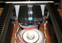
I finally got around to testing the control & protection board, and did the final assembly of my F5X over the weekend. I've got it nice and stable at 1.5A bias. Heatsinks are settling in at a max temperature of 62 Celsius inside my 25 degree room.
Absolutely loving the sound so far!
Absolutely loving the sound so far!
Protection board works great. I've got it all wired and ready to drop in the regulator as well in the future.
I really love the tight bass and smooth natural highs. A definite improvement even with my little B&W bookshelf speakers. Even at 1.5A bias, this amp makes a great room heater!
Here are some photos (need to clean the front panel):


I really love the tight bass and smooth natural highs. A definite improvement even with my little B&W bookshelf speakers. Even at 1.5A bias, this amp makes a great room heater!
Here are some photos (need to clean the front panel):
Many thanks for the pictures. Looks great.
Did you get the front panel engraved, or it is sticker ?
And I am most happy to know that the protection board works, after all the hassle.
So for all the GB1 & GB2 subscribers, there is no reason not to build.
Don't underestimate the B&W book shelves.
I also used a B&W CDM1 with modified crossover until recently replaced by the Accuton CELL.
See also Markus's post #654.
Oh, you should clean your finger-prints with ethyl alcohol.
Patrick
I had the front panel engraved by Front Panel Express here in the US.
I was a little worried about soldering the SMD parts on the protection board due to my lack of experience with SMD. With good liquid flux, small diameter solder and a small soldering iron tip it went very well. The fix was not terribly hard either. I'd just recommend everyone use a very sharp knife and take your time and go slow.
Really loving this amplifier and looking forward to building the matching preamp down the road.
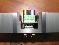
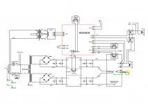
Protection Board
Horio,
Looks great!
Do you remember where you got your protection board jumpers and sockets, and possibly the part #'s? I have been trying to get the right parts, but without the hard copy catalogs for digikey or mouser it has been really tough to find the right parts.
Matt
Horio,
Looks great!
Do you remember where you got your protection board jumpers and sockets, and possibly the part #'s? I have been trying to get the right parts, but without the hard copy catalogs for digikey or mouser it has been really tough to find the right parts.
Matt
Matt,
I skipped using the connectors for all of the various relays and soldering small gauge stranded wire right to the board. Here are the Mouser part numbers for the jumpers and sockets I used for the control board selections:
3x2 Male Socket: 649-67996-106HLF
Shunt Jumpers: 649-63429-202LF
I skipped using the connectors for all of the various relays and soldering small gauge stranded wire right to the board. Here are the Mouser part numbers for the jumpers and sockets I used for the control board selections:
3x2 Male Socket: 649-67996-106HLF
Shunt Jumpers: 649-63429-202LF
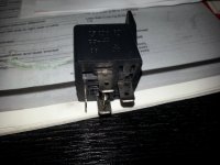
Few questions :
1) will this relay work as well in the protection circuit?
2) the protection board just need a couple of resistors change as in Patrick's write-up and we don't have to cut the board as in what Nic has done. Is this correct?
Thanks
1) will this relay work as well in the protection circuit?
2) the protection board just need a couple of resistors change as in Patrick's write-up and we don't have to cut the board as in what Nic has done. Is this correct?
Thanks
Attachments

- Home
- Amplifiers
- Pass Labs
- F5X -- the EUVL Approach - The Build Thread