Sigh, I wish I could see your links from work. Will have to wait until I get home. It sounds like Q1 is not oriented properly.
I do not have a detailed idea on how CD-RW detection is working. I can only speculate that this is based on High Frequency signal level. This should be in direct relation with reflection degree witch is for CD-RW 10-25%, CD-R 40-70% while a pressed original CD have 70-90%.
The rest is done as you mentioned from datasheet:
78601-pin53 pull 9242-pin38 high and increase 9242 HF gain.
Regards,
Tibi
I did some more research and such information should be available in subcode Q-channel. So from the very beginning, in Programing Memory Area, the type of CD media should be presented to CD unit.
As per ECMA-395:
"5.4.1 Contents
The PMA can contain the following types of information:
1: Track numbers with their start and stop time. This is the table of contents for the partially recorded disc. The Track numbers of all Tracks (including Reserved and Incomplete Tracks, see chapter 5.4.1.1) in the PMA must be contiguous and increment by one.
2: Disc identification. A 24-bit binary number shall be recorded in the disc to identify each disc.
3: Skip information (optional). It is possible to indicate that an entire Track or a part of a recorded Track (a time interval) should be skipped during play back of the disc. The Skip feature is defined for Audio Sessions only.
4: The RID code in the User Data field of the blocks for Table Of Contents Items."
I other words, if there is a CD-RW, after subcode Q-channel decoding in LC78601, a flag is raised to ASP LA9242 in order to adjust gain and make CD readable.
Regards,
Tibi
See also:
Orange-Book standard (rainbow)
http://www.ecma-international.org/publications/standards/Ecma-395.htm
Last edited by a moderator:
And now I have two working remotes. Tibi, I cannot believe that's how you intended this part of the PCB to be laid out for the transistor.
Thanks.
")
Sigh... I started with testing the CDRW switching on my mind and ended up setting up a second salas psu for the motors...
Not that big of a difference to be honest (certainly not as big as using one for the digitals), but I must admit that it really needs some measuring and fine tuning. Perhaps even a boost in current since I ve seen its leds go off because the motors at some points pull too much current... It s currently set at 700mA. I ll probably go for 1A and add some extra decoupling cap right on the entrance of the pcb to help with spikes.
Not that big of a difference to be honest (certainly not as big as using one for the digitals), but I must admit that it really needs some measuring and fine tuning. Perhaps even a boost in current since I ve seen its leds go off because the motors at some points pull too much current... It s currently set at 700mA. I ll probably go for 1A and add some extra decoupling cap right on the entrance of the pcb to help with spikes.
And now I have two working remotes. Tibi, I cannot believe that's how you intended this part of the PCB to be laid out for the transistor.
Thanks.
Yep, this is my fault.
BTW, remotes are shipped with a 100mA LED. Remote will work in any angle and position even from 25m.
Regards,
Tibi
For a couple of days now I am playing CDs using the Sanyo mecha. Its quality is quite higher than the cheaper one. The spindle is perfectly centered and the sled comes pre-lubricated, while the plastic shielding adds to the overall vibration control.
...
Hi Dimitris, how did you connected the Sanyo SF-P101N (5/8) with the 16 pin cable..
regards
Raimund
I got the 16pin version
can you tell me where did you get the 16 pin version ..
regards
Raimund
I got it from here
New Genuine Sanyo SF P101 16P Deck Old Version Laser Head Optical Pickup | eBay
Please note that he s using Swiss Post and in many cases it can be really really really slow...
It took mine 45 days to arrive...
New Genuine Sanyo SF P101 16P Deck Old Version Laser Head Optical Pickup | eBay
Please note that he s using Swiss Post and in many cases it can be really really really slow...
It took mine 45 days to arrive...
I have just replaced the stock C11 with a Cornell Dubilier Mica 1nF cap trying to fix my CDRW reading issues.
The increase in detail, grandeur and spatial sense was big enough to be compared to the one I had when I first upgraded the stock C8.
The cap I use is this one
CM06FD102FO3 Cornell Dubilier | Mouser
However, the mechanic became even more intolerant of CD imperfections. And CDRWs are even less readable now...
Anyway... consider me a happy diyer
I don t have that many CDRWs anyway...
I think it s time I started working on the enclosure...
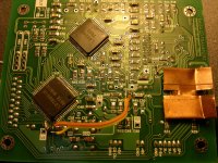
Oh by the way, I also got some small heatsinks to mount on the bridge chip. However, they do not come with an adhesive tape or anything... Any idea how to mount them? Should thermal paste be enough? They are pretty small and light.
The increase in detail, grandeur and spatial sense was big enough to be compared to the one I had when I first upgraded the stock C8.
The cap I use is this one
CM06FD102FO3 Cornell Dubilier | Mouser
However, the mechanic became even more intolerant of CD imperfections. And CDRWs are even less readable now...
Anyway... consider me a happy diyer
I don t have that many CDRWs anyway...
I think it s time I started working on the enclosure...
Oh by the way, I also got some small heatsinks to mount on the bridge chip. However, they do not come with an adhesive tape or anything... Any idea how to mount them? Should thermal paste be enough? They are pretty small and light.
Last edited:
Oh by the way, I also got some small heatsinks to mount on the bridge chip. However, they do not come with an adhesive tape or anything... Any idea how to mount them? Should thermal paste be enough? They are pretty small and light.
You can use a thermal adhesive such as Arctic
Arctic Silver Thermal Adhesive
I have just replaced the stock C11 with a Cornell Dubilier Mica 1nF cap trying to fix my CDRW reading issues.
The increase in detail, grandeur and spatial sense was big enough to be compared to the one I had when I first upgraded the stock C8.
The cap I use is this one
CM06FD102FO3 Cornell Dubilier | Mouser
However, the mechanic became even more intolerant of CD imperfections. And CDRWs are even less readable now...
Anyway... consider me a happy diyer
I don t have that many CDRWs anyway...
I think it s time I started working on the enclosure...
Oh by the way, I also got some small heatsinks to mount on the bridge chip. However, they do not come with an adhesive tape or anything... Any idea how to mount them? Should thermal paste be enough? They are pretty small and light.
What have you replaced at C11 position? There is no cap at C11 on my PCB, is that optional?

Last edited:
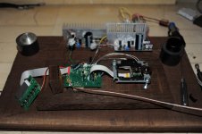
I have started working on the chassis.
The base is a piece of wenge wood 35x15cm and 2.7cm thick.
The mecha is held in place using M6 screws and the base is on top of some nice metal cones I have.
I have also removed the plastic headers and soldered the motor cables straight to the pcb. The cable I used is a very nice quality silver ribbon wire with its conductors separated in couples. I need to attach them to the base to prevent them from crosstalking to each other. Same for the 5V supply and I will do the same for the 8V too eventually.
The PSUs will be on a separate chassis and connection will be through a 4pin XLR socket.
Attachments
A new GB is open http://www.diyaudio.com/forums/group-buys/238895-shigaclone-new-gb-2013-a.html#post3557018
Same prices as on 2012 GB.
I started to redesign the PCB and also few new improvements will be added.
I'll need three beta testers. Each beta tester will receive a free full kit ( all parts, not mounted) to extensively test, measure, compare and provide feedback.
Beta testers need to have a minimum measurement equipment (oscilloscope, DMM etc) and also a Shigaclone (modified or not) for direct comparison.
Good SMD soldering tools and skills are also required.
I also expect that beta testers to be very active on forum and later provide further forum support to GB users.
Pls send me an e-mail if you want to be a beta tester.
Regards,
Tibi
Last edited by a moderator:
Is LC78622. Could be better, for shure different.
From the tehnical point of view it is harder to implement than LC78601. By using an external MCU and display section it gives more design flexibility, but will increase costs. For example we can extend CD servo functions, display more information and we are no more stuck on a multiplexed LCD.
Having separate MCU and display section may offer better DSP functionality and the transport may sound better.
From marketing point of view will be a great improvement.
Regards,
Tibi
Are these improvements you will be adding????
Are these improvements you will be adding????
There is still lot of juice to squeeze fm LC78601. For the time been Shiga MKII will stuck to LC78601.
LC78622 add also more error correction. This may lead to more jitter ... will see, there are other options too.
Regards,
Tibi
After a long time with the 12nF FT-2 teflon cap on C8, I suddenly decided to try something different.
A 0.22uF FT-3 teflon cap. This was quite irrational to what the propositions for the spot are, but the results are quite interesting and confusing...
In a word and after a very fast audition with the cap still quite freshly soldered and non-broken in, it feels that the sound is more... Class-A for a lack of a better word.
The mids and bass seem more detailed, articulate and forward.
One thing I did not like with the 12nF teflon was that highs sounded too big and impressive. Some times it felt like having a huge ride hat in the living room and a huge drummer was banging it hard with a huge drum stick
Now highs do not sound that impressive, but still have much detail while their size and positioning feel much more natural.
I felt something similar with an electrolytic manamanam gave to me, but the detail suffered significantly.
Unfortunately it is late here for more proper auditioning. I will give the new cap a few weeks and get back to you.
I also want to try to bypass the 0.22uF with the 12nF and see what happens
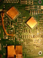
One modification to enhance CD-R, CD-RW and SACD reading.
One modification to enhance CD-R, CD-RW and SACD reading.
Recently I got a SACD on which my Shiga refused to read TOC whatever I do.
I started to dig into problem and found one layout problem. This will be corrected in MKII.
C50 - 680pF and Q3 feed pin 59 - LF2 on LA9242. Quoted from datasheet:
"The mirrored surface level is maintained by the capacitor for LF2 (pin 59) ; when a drop in the EFM signal (RFSM
output) reaches 0.35V or more, a high signal is output to DEF (pin 49). If DEF (pin 49) goes high, the tracking
servo enters THLD mode. In order to prevent the tracking servo from entering THLD mode when a defect is
detected, prevent DEFECT from being output by either shorting DEF (pin 49) to GND, or shorting LF2 (pin 59) to
GND."
Therefore, even is not mentioned in any datasheet, C50 must be as close as possible to LC78601 pin - 47.
Q3 must be also as close as possible to C50 in order to avoid any spurious noise to get in.
C45 - 100 pF is there to reject any VHF noise on Q3 and must be as close to Q3 as well.
For me, moving C50 - 680pF and Q3 did the trick and now my unit read TOC without any problem even on the most dirty and old disks which are constantly rejected by a NAIM CD5 XS.
Please note that the pcb trace after LC78601 pin 47 must be cut as well, otherwise will act like a small antenna and this modification will have no effect.
Regards,
Tibi
Attachments
Last edited by a moderator:
- Home
- Source & Line
- Digital Source
- Finally, an affordable CD Transport: the Shigaclone story