>"crap"
Care to substantiate?
Hi Edmond,
That was the least important part of the message; I have no ill against TPC or TMC
")
Using Blacks formula: F(s)= G(s)/1+G(s) H(s) if G(s) = N(s)/D(s) then
F(s) = N(s)/(D(s) + N(s)H(s))
Thanks for the review of this, perfectly timed because it came just as I looked at the non-minimum phase behaviour of a real amp.
A fairly conventional circuit but the positive zero caused a small reduction of stability.
I like the term "positive" zero. Less arbitrary than RHP
Best wishes
David
I'm not going to take the bait, Mike. <snip> I do notice that you and Waly seem to disagree on this matter. so I suggest that the two of you duke it out. That will provide us some needed entertainment.
I'm not going to take the bait, Mr. Cordell. I'm afraid you will have to go and entertain yourself elsewhere.
Last edited:
Bob, here is that .asc. Note that i use zetex models and KSC2690A/KSA1220A and Andy_C's MJL3281A/MJL1302A models which in my experiance are good models. I can send them to you by email. If you're interested send me mail.
I simulated this circuit using simetrix.
First , the Zetex transistors show very high beta > 500 ,
i find that it s quite a lot for 200V average power bjts
but once you replace the VAS/TIS ones with BC546A ,
wich are more completely modeled , the circuit start
to oscillate.
With the Zetex OLG at the origin is 175dB or so ,
collapsing by 40dB with models that seems somewhat
more realistic.
The Zetex datasheet says beta 300-800 for Ic=10mA, so I don't think 500 is outstanding. VAF is 450V, which could explain the larger OL gain (BC546A has only 128V), since the input stage is also loaded by VAF/gm.
But otherwise, I trust the Mike/Zetex models as much as Mr. Cordell's. I haven't seen any kind of validation on either side, other than "because I say so" and some vague reference to undisclosed DC measurement methodology and results (not to mention that DC related parameters are, for the most, telling the DC side of the simulation story, so not much about ULGF, stability, etc...). At least Mr. Cordell corrected a few obviously stupid parameters in the (in)famous OnSemi models.
I though have to agree that if the stability of an audio amplifier flips depending on the chosen input stage devices (in the same class, like BC546 vs. ZTX796) then the design is rotten, to start with.
The Zetex transistors I use tend to have a high beta; check the data sheets.
The ones i use are the same as yours , they are provided
with symetrix though i ve got another source that end
being the same files , only a few devices are added.
The 450 VAF pointed by Waly is the good value for the PNP ,
(120 for the "complementary").
These have lower FT than the BC546 , hence the peak
added by the output stage is very pronounced with thoses
transistors , all is solved once the common emitter of the
VAS/TIS is slightly degenerated with 10-20R , this tame
any oscillation , at least with resistive load.
These have lower FT than the BC546 , hence the peak
added by the output stage is very pronounced with thoses transistors , all is solved once the common emitter of the VAS/TIS is slightly degenerated with 10-20R , this tame any oscillation , at least with resistive load.
I find that degenaration of the TIS only helps if an inordinately large resistor value (~100R) is used. Smaller values (~22R) I find simply worsen minor loop stability margins.
Thanks for the review of this, perfectly timed because it came just as I looked at the non-minimum phase behaviour of a real amp.
A fairly conventional circuit but the positive zero caused a small reduction of stability.
I like the term "positive" zero. Less arbitrary than RHP
Best wishes
David
Thanks for your comments.
I look forward to read your paper in LA.
JPV
Thanks kgrlee for your post.Thanks for this, JPV.
It is the best accurate explanation of plain Miller I've seen. Your clarity approaches that of Great Guru Baxandall. I shall now pre10 2 unerstan it to bolster my facade as a (pseudo) guru and use it confound the truly pseudo pontificating that abounds.
______________________
Mike, you have demonstrated loadsa stuff. Alas ALL your demos (at least the SPICE sims) seem to have appalling THD & stability. IMHO, none of them would be stable with 'real life' loads.
Few of us are concerned with the difference between pig sh*t and cow sh*t. Apples & oranges would be better compared in something with some semblance to a 'good' amp.
Bode plots on sims of wonky amps look testicle but it would be good to show improvements of your beloved TPC against TMC on something with 'good' performance. 'Real life' would be nice but you seem to spurn any such evidence.
In the meantime, SPICE THD & stability with different loads will do for a start.
______________________
Waly, if I read you correctly, your 'reliable measurements' are solely about Loop Gain and Phase Margin. Can you confirm this?
I'm rather saddened that you discount the efforts of those who at least attempt 'real life' measurements. I for one am far more interested in these than dubious pontificating by various pseudo prophets.
While I'm happy to generate pages of semantic and pedantic diarrhea, I'm under no illusion that these even approach the practical usefulness of my 'Definitive Dissertation on VAS vs TIS'
As you are a Budding True Guru, I counsel you not to indulge in Excess Phase less you join the ranks of pedantic pseudo prophets.
It is always a pleasure to read somebody who can comment with ' grano salis'
JPV
Folk's interested in the singularities and frequency response of the TIS should read Prof. Michael Tse's lecture notes below:
http://cktse.eie.polyu.edu.hk/eie304/FrequencyResponse.pdf
http://cktse.eie.polyu.edu.hk/eie304/FrequencyResponse.pdf
I find that degenaration of the TIS only helps if an inordinately large resistor value (~100R) is used. Smaller values (~22R) I find simply worsen minor loop stability margins.
Once we use other models your circuit oscillate unless
said 10-20R is implemented , did you try your own schematic
with other transistors.?
As already pointed , one cant rely on a design that is device
dependent , moreover when using schematics as exemples
for demonstrations , this just introduce useless hassles when
discussing eventual observations.
Well Michael, this is Classic coming from youThis is a classic Bob Cordell cop-out: you reject hard evidence provided without providing grounds for doing so, or even checking its reproducibility or veracity, and then refuse to provide evidence to back up your unsubstantiated averments.
You seem to reject ALL 'real life' evidence .. especially when it doesn't tally with your wonky theories. Are one of those that believe 'real life' can't be true cos it dun relate to your pontificating? Is 'hard evidence' for you sims using your wonky models?
I'm not sure if replicating your sims is fruitful. Most of us are interested in BETTER THD & stability. Your examples always seem to have wonky THD & stability. IMHO, all of them would be unstable with 'real life' loads.
If you have posted some sims with 'acceptable' performance and what you think is acceptable stability in 'real life', I'd be interested ... but please post your sim results first.
Actually Dave, I asked the question cos Waly said 'real life measurements'. IMHO these, however crude, are more important than any dubious pontificating by pseudo prophets. Waly's answer allows us to give his statements their proper importance.The approximation is often made that the distortion reduction must be proportional to the Loop Gain.
This is not true universally. Bode realised this back in 1939 and discussed it in detail.
Cherry worked a practical example in his 1982 JAES articles and showed it does not apply to most parameters for a typical audio amplifier.
I know Richard Lee is a Cherry fan and I assume his question is because he has picked up on this too.
This is reason for my frequently repeated comment that TPC and TMC are only equivalent to first order.
At least he does do some 'real life' stuff. It would be very sad if a bright young man like him goes the way of the pseudo prophets who claim their dodgy sims are the answer to life the universe and everything.
Hopefully, his present rather offensive manner will mellow with age and he will develop into a sage, renowned not only for sagacity ... but also for generosity and gentlemenly behaviour .. like GG Baxandall and Bob.
_______________
As you point out, the 'real life' evidence is .. of those who have sim'd TPC & TMC, either with MikeK's naive methods or something more optimal for the two methods, have found an advantage, some bigger than others, with TMC.
An even more telling 'real life' point is that those who have built (ie 'real life') these have found it holds too.
Of course there are pseudo prophets for which good THD and 'real life' stability are of no importance if the circuits do not conform to their Holy Book ... whether sim or 'real life'.
Err.h! Bob has a couple of chapters in his book on the subject and his models are clearly the result of his methods.But otherwise, I trust the Mike/Zetex models as much as Mr. Cordell's. I haven't seen any kind of validation on either side, other than "because I say so" and some vague reference to undisclosed DC measurement methodology and results (not to mention that DC related parameters are, for the most, telling the DC side of the simulation story, so not much about ULGF, stability, etc...). At least Mr. Cordell corrected a few obviously stupid parameters in the (in)famous OnSemi models.
As you appear to be an expert on dreaming up SPICE models, perhaps you can let us in on your secret methods. Care to tell us which ones you trust and why?
____________________
michaelkiwanuka said:I though have to agree that if the stability of an audio amplifier flips depending on the chosen input stage devices (in the same class, like BC546 vs. ZTX796) then the design is rotten, to start with.
Waly, presumably, you are now going to astound us with your design that is completely immune to device changes and has SOTA THD, stability on all loads, bla bla ... and in 'real life' too.Waly said:I though have to agree that if the stability of an audio amplifier flips depending on the chosen input stage devices (in the same class, like BC546 vs. ZTX796) then the design is rotten, to start with.
Us old fogeys who have been involved in commercial design will fall at your feet at this demo of the Holy Grail
OK. Just sim will do for a start.
Michael, there is no need for you to demo this. Your own efforts are perfect examples of your self named 'rotten designs'. Also I'm not sure Zetex appreciate your demonstrating that naive substitution of their devices in a good circuit miraculously gives it poor THD & stability.
It is the best accurate explanation of plain Miller I've seen. Your clarity approaches that of Great Guru Baxandall. I shall now pre10 2 unerstan it to bolster my facade as a (pseudo) guru and use it confound the truly pseudo pontificating that abounds.
JPV, only the last part needs salt. The first bit is quite factual.It is always a pleasure to read somebody who can comment with ' grano salis'
Re - RHP
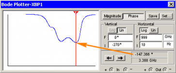
I'd never heard of RHP Zero until mentions of it in this thread. After looking @ the FrequencyResponse.pdf linked by michaelkiwanuka http://cktse.eie.polyu.edu.hk/eie304/FrequencyResponse.pdf i examined my Enhancer circuit http://www.diyaudio.com/forums/solid-state/238449-thd-loop-gain-enhancer.html
Yes the phase is "rather" extended but that's just to see what it shows. I doubt that in a real Amp etc, even with the worlds best oscilloscope, we could witness such HF plots with real audio circuits ?
I noticed that the phase never reached 270' only 147' ? There do though "appear" to be some similarities between my phase plot & the ones in the PDF. I don't pretend to understand it all, or anywhere near, i'm just attempting to establish whether there is "something" worthwhile exploring further in RHP ?
An explanation of what i'm seeing, would be welcome
I'd never heard of RHP Zero until mentions of it in this thread. After looking @ the FrequencyResponse.pdf linked by michaelkiwanuka http://cktse.eie.polyu.edu.hk/eie304/FrequencyResponse.pdf i examined my Enhancer circuit http://www.diyaudio.com/forums/solid-state/238449-thd-loop-gain-enhancer.html
Yes the phase is "rather" extended
but that's just to see what it shows. I doubt that in a real Amp etc, even with the worlds best oscilloscope, we could witness such HF plots with real audio circuits ?I noticed that the phase never reached 270' only 147' ? There do though "appear" to be some similarities between my phase plot & the ones in the PDF. I don't pretend to understand it all, or anywhere near, i'm just attempting to establish whether there is "something" worthwhile exploring further in RHP ?
An explanation of what i'm seeing, would be welcome
Attachments
An explanation ... would be welcome
Hi
The link is excellent. I found and read it a few years back and re-read it when reminded by Michael's post. Thanks to him for that because it was helpful to read it second time. So you probably need to read it a few times too
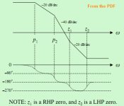
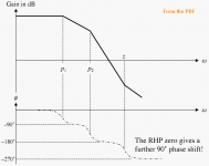
RHP zeros are practically never desirable in an amplifier so it is worth the effort to eliminate them. In a conventional amplifier the only one is likely to be caused by the VAS aka TIS. Usually not a problem because it is above any frequency of interest.
It is possible for a particular combination of reasonable component choices to result in the RHP zero frequency to be sufficiently low to affect the stability a little. This can occur if the LTP emitter resistors are fairly low (to reduce noise probably) compared to the VAS/TIS emitter resistor (used for over-current protection, often).
If your circuit is unconventional then normal rules-of-thumb won't help. But I doubt a RHP at >3GHz will hurt.
Best wishes
David
Last edited:
Yes the phase [frequency? - HarryDymond] is "rather" extended
Please do not waste your time simulating to 1 THz. What you are seeing bears no resemblance whatsoever to what you would see in "real life". Unless you have specific distributed models for every single component in your schematic, including circuit board traces, don't bother going above about 200 MHz (even at this frequency you need at least some modelling of circuit board traces).
I hope by reading the reference from Michael that you realise that to get anywhere with AFEC, circuit analysis (aka maths) is required.
Last edited:
I though have to agree that if the stability of an audio amplifier flips depending on the chosen input stage devices (in the same class, like BC546 vs. ZTX796) then the design is rotten, to start with.
I don't agree. A production amplifier should be tolerant of the expected variations in a given device's parameters, not of arbitrary replacement of devices with other model numbers.
On this subject, can anyone show how in LTspice to vary component parameters in a loop-gain simulation? The loop gain simulation itself involves stepping a parameter and then using trace maths to combine results from the steps. If another level of stepping is introduced (to vary a component), how do you ensure the correct steps are used in the loop gain calculations? To put it another way, what I want to achieve is a family of loop-gain curves with a component value as a parameter. Any ideas?
Last edited:
- Home
- Amplifiers
- Solid State
- Bob Cordell's Power amplifier book