I realised this when I was checking the bias this morning and couldn't get the levels I wanted. I then noticed that the mains voltage was very low and the supply fell to +/-34 V when the amp stopped responding to the bias control. A quick simulation revealed the sensitivity to the supply voltage.
To me these sound somehow weird.
The amplifier had power supply from 24V rail voltage to 51V rail voltage without any mode on the PC boards.
Here I do not talk about just a simple test, with that PS was used months.
I had never issue with the bias set up.
With 3 pair power darlington these amp was heavily biased into Class A ( up to 3A) at 24V rail voltage.
At 51V only was used only a pair darlington (from Texas Instruments, and Philips) less than 50mA bias setup.
I could adjust the bias precisely under the mentioned rail voltage without any mode on the PC board.
The 3A bias was set up with a cheap (not price wise, junk quality) BDW83D/84D after I tested those devices and I didn't like them at all.
So I swapped the PS transformer from 30VAC to 18VAC, also used a huge heatsink I biased the amp just to see if it will perform better.
Very minimal sound improvement because the high bias. Changing parts on the PC board (or choosing the right quality parts) has way more influence on the sound than the bias over 50mA up to 3A.
What I realised over the years we can not pick just any semiconductor for replacement to any stage without having more or less influence on the sound of the amp.
Again to me something new these bias setup problem..

Greetings G
Hi Gabor ,
I m sure at 100% that thoses resistors bring absolutely nothing ,
moreover with F5/Profet whose caracteristics are only transistors
dependent , so dont waste money on devices that are hyped
and wich have far less influence than the layout.
Once Ashok or Bigun try the Sankens we ll have an idea
of how they perform , i ll also use thoses devices to check
this amp s eventual bugs.
wahab
when first I built the ProFet I did like a lot. Until I rebuilt and compared with the Darlington amp.
Also one of my friend built the amp and anybody who had the chance to listen like her alot.
Because these amp uses a fee component I thought here I can test some of my favorite resisters, or different type of LatFet.
Usually I use DALE resistors for test purpose. After I ordered Caddock, Japanese Takman etc.
Also I tested with Hitachi & Exicon mosfet.
Some exotic caps were used to but on the end I settled with the Russian PIO.
Yes I got some over all sound improvement and some experience but on the end when I compared with the Darlinton I have to say it was a huge waste of money that investment.
So I already done those investment and test, now to late.
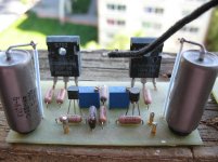
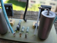
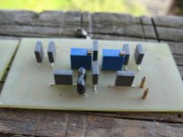
I post some picture from the ProFet with different type of resistors and LatFet.
Did I learn something, yes not to go after some other guys specially from Mr Pass forum, but not just from there.
Also to pick a amplifier I like and use it as a benchmark amp compare any new amp I build o that.
Because these happened several time now I think twice to invest more and more fund some of my project.
For example I do like the sound of the darlington but over the years I spent so much on component specially on semiconductors (because some of the original no longer available) now I think twice to invest into the Sanken darlingtons or other device without knowing that will improve the amp.
Bigun
I think wahab would like to get some feedback from other people on the project that is why he wrote to wait until you or Ashok will test the amp.
I would love to get my hand on a pair of those Sanken to test it but we want your experience to on the project.
Right now I do have several project to test among them these amp modded by wahab!
Otherwise I'm happy with the sound I got now I mostly want to improve the stability but in the same time the overall performance will be improved that would be an extra.
Now I plan to rebuild these amp into a mono block. Right now I will keep these amp with BJT output that sure.
Of course I will test it with mosfet to.
But that later.
Yes I built more than 100 amplifier over 24 years or so.
That is what happens when we switch music listening to amplifier building hobby.
Greetings G
Attachments
Hi G,
Setting the bias isn't so much of a problem. In my case I had a limiting resistor in the variable resistor leg that would normally not matter. But at +/- 34 V supply it was too high in value and would not allow the voltage to turn on the output stage. But it did indicate that the bias varied with supply voltage.
At higher supply voltages the bias would go beyond what was set at a lower voltage. With a mains supply that is not reliable one needs to take care of this.
As I mentioned a regulated supply for the input stage drastically reduced the sensitivity of the output bias to varying dc power supply voltage.
Others have also used a zener on the input stage supply of similar circuits to solve this problem.
I will try it out. Now I'm off. Lots of work to get done today.
Cheers.
Last edited:
I added the zener stabilised supply for the input transistors ( 18 V).
Now the amp works Ok at low supply voltages ( +/- 33V in my case ).
Bias also seems more stable but isn't OK yet. Up to about 55 deg C at the heat sink seems to be tolerable. But if one gets up to 65 deg C the current slowly builds up. But then I'm cheating as I clipped the output quite a bit and ran the amp into 4 ohms. So maybe under normal use the temp will never go that high. I've been bogged down with several things so I am unable to check this out quickly. I might add that the heatsink was painted black and that isn't as good as an anodised sink. I also faced the sink with fins facing down. That restricts air flow and hence all the hot air travels up to the base of the sink reducing the sinks dissipation capabilities. Not a good thing to do but I was trying to push up the sink temp quickly as I had limited time to check the results.
I guess everyone is aware that we are only concerned about the bias current of the bipolar output stage version of this amp. The LatFET is intrinsically stable .
I must say the bass of the amp is very good. Nice, very deep and tight......punchy. Voice is also very good especially female vocals. Clapping sounds very realistic. Has a natural sound unlike many systems. Treble is crystal clear when the source is good. Very nice. But I plan to do more comparisons after a couple of weeks. I'm running it without an input cap. Will try a different cap at the NFB point. I've two more brands.
By the way the output offset drift is well within limits. No problem there.
Things are going well. I might add that for watts/cm sq of heatsink , I've exceeded what most DIYer's are using. So maybe with a larger sink and two pairs of output devices this temp sensitivity will be well under control.
So has anyone else made a board and tested this circuit ?
Last edited:
Member
Joined 2009
Paid Member
So has anyone else made a board and tested this circuit ?
I remain interested. I have a heatsink and a pcb with 7 pairs of the Sanken Darlingtons bolted to it along with a pcb full of amplifier (TGM6 - altogether 7 channels). I need to end up with 5 amplifiers on this heatsink and I don't have space to use my TGM5 symmetric amplifier design (not do I want to build 2 more of those SMD pcb's in the same style - I like to move on to a new design). I desoldered the Sanken devices and Vbe multiplier devices from the edge of the pcb and removed the pcb. Now I just have the heatsink with Darlingtons and Vbe multipliers bolted down with mica washers and thermal grease. This is the same one I show images of in my TGM6 amplifier thread. I have also started to prepare a chasis - it's an old Fisher amp chasis and it needs some work.
I haven't decide what amp I'm going to put on this heatsink yet - I'm very curious about the P3A amplifier so I may end up making a single channel mock-up of both designs to see what I like and which suits the best. I am currently favouring the symmetrical topology of the amplifier we're discussing in this thread. Time is not on my side for the next while - I have a few weeks of travel to Asia and other places but I will continue to do some simulations and some planning towards the time I can get the soldering iron turned on again.
Last edited:
I added the zener stabilised supply for the input transistors ( 18 V).
Now the amp works Ok at low supply voltages ( +/- 33V in my case ).
Bias also seems more stable but isn't OK yet. Up to about 55 deg C at the heat sink seems to be tolerable. But if one gets up to 65 deg C the current slowly builds up. But then I'm cheating as I clipped the output quite a bit and ran the amp into 4 ohms.
So maybe under normal use the temp will never go that high. I've been bogged down with several things so I am unable to check this out quickly. I might add that the heatsink was painted black and that isn't as good as an anodised sink. I guess everyone is aware that we are only concerned about the bias current of the bipolar output stage version of this amp. The LatFET is intrinsically stable .
I must say the bass of the amp is very good. Nice, very deep and tight......punchy. Voice is also very good especially female vocals. Clapping sounds very realistic. Has a natural sound unlike many systems. Treble is crystal clear when the source is good. Very nice. But I plan to do more comparisons after a couple of weeks. I'm running it without an input cap. Will try a different cap at the NFB point. I've two more brands.
By the way the output offset drift is well within limits. No problem there.
Things are going well. I might add that for watts/cm sq of heatsink , I've exceeded what most DIYer's are using. So maybe with a larger sink and two pairs of output devices this temp sensitivity will be well under control.
So has anyone else made a board and tested this circuit ?
I also faced the sink with fins facing down. That restricts air flow and hence all the hot air travels up to the base of the sink reducing the sinks dissipation capabilities. Not a good thing to do but I was trying to push up the sink temp quickly as I had limited time to check the results.
If the heatsink fins are face done that cut the heatsink dissipation capabilities less than half about 1/3
If face up that is around half effective or a bit more than half..
At normal position I would use min. 2PC heatsink like yours for 1 channel with 2 pair power transistor especially if you use sometimes 4Ohms speakers.
I'm happy you like the sound, it will get better when you run the amp about 100 hours or so.
Also choosing the right quality components and match them together has lot of effect on the sound.
Please try to remove the 2PC 100K resistor in case you didn't did already.
Offset drift to me so min. not even worth to talk about.
With large enough heatsink you can bias the amp 100mA or even higher 150mA but to do that need 2 pair darlington.
Of course all depends how hard you push the amp.
I do like to have some safety margin, keep the temperature always under 50C..
I do have some TO3 case ON semi darlingtons and also got some ST type BDW83C/84C to.
Soon I test those to, today I worked on a large Class A amplifier enclosure.
Also if I get some Sanken at local store I will test them to.
Those are not so expensive how I thought at first.
Thank you for your feedback..
Greetings G
Member
Joined 2009
Paid Member
Also if I get some Sanken at local store I will test them to.
Those are not so expensive how I thought at first.
I wait eagerly for any impressions you have from these devices.
The kind that I have is: http://www.sanken-ele.co.jp/en/prod/semicon/pdf/2sb1560e.pdf
They are $3.57 each in single qty from Digikey (I bought a pair recently).
They are $3.57 each in single qty from Digikey (I bought a pair recently).
To order from Digikey the shipping cost more than the transistors.
I will check it at the local store where I used to buy parts.
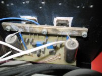
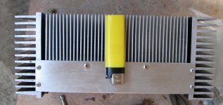
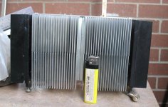
These is the heatsink I will use after all my test done.
By the way I'll build two separate mono block, the heatsink & Pc board on the top probably the caps to..
I will see.....
Greetings G
Attachments
Member
Joined 2009
Paid Member
Finally the Lat FET's !
In spite of all the work I have had I managed to , finally, remove the bipolar Darlingtons and replace them with Hitachi 2SK1058/2SJ162 latFET's.
I got blue smoke !!
Luckily I had used 10 ohm protection resistors in the fuse holders. They burnt up dramatically. I spent a long time trying to figure out what was happening and burnt a few more resistors ( those in the fuse holder!).
Finally while I was checking the devices it suddenly dawned on me that the LatFET pin out isn't like the IRFP MOSFET's ! I had forgotten that it was Gate Source Drain from left to right. I haven't used one in a long time ! So I had interchanged the Drain and Source leads.
I fixed that and the amp worked fine ( the devices were not damaged). The sound is very good like the bipolar version but I felt that transients like the kettle drum etc., had a bit more bite without being harsh. Voice is just as good and about deep bass I'm not certain. It does go very low and is tight but is the bipolar tighter /and a shade deeper?
I can't judge as I used the same pcb for this one. I'll have to remove the power transistors again to check this one. It has to be a level adjusted A/B comparison which I can't do now. But I like both but would build the LatFET version due to the apparent crisper transient reproduction . I am not using an input capacitor. The signal comes direct from the Bluray player via an Alps volume control. The power supply has 2x10,000uF caps per rail ( so total of 4x10,000uF )
Now I will have to build a stereo version of the bipolar and the LatFET circuit and do an A/B comparison. If I had to choose without any more testing I'd pick the LatFET version for reasons mentioned above and the fact that I needn't worry about dc bias stability.
So finally I can use my precious stock of 2SK135/2SJ50 and 2SK134/2SJ49 !
In fact I have a whole lot of plans around this module. Plenty of testing to do. It's going to be exciting !
I guess I'll also have to build a P3A also just to compare and see where each one stands in relation to each other.
Trust many others are also building this amp . I'm guessing that someone will come up with some comparisons with other amps.
I still have to try out the discrete Darlington ! Maybe I should do it now, before this board gets damaged or 'lost'!
Listening to Sade right now. Sounds very good !
Last edited:
Member
Joined 2009
Paid Member
Nice work Ashok - I think there's a saying "after great trouble comes the truth" so some smoke along the way is a good sign maybe...
Since the FETs are easy to parallel you might try an extra pair - the bass may improve further, but you may lose some definition somewhere else.
Keep going !
Since the FETs are easy to parallel you might try an extra pair - the bass may improve further, but you may lose some definition somewhere else.
Keep going !
Hi Andrew,
I always think of rigging up a bulb and switch permanently as experimentation sometimes happens suddenly. But like many things it hasn't happened yet ! Maybe this time I should do this quickly. Loosing Lat FETS is a GREAT loss ! Not just the money but it's so hard for me to get them !
Bigun. Yes a parallel set of transistors might help the low end. But let me get some boards made that can accept both devices and then compare them. The LatFET really sounds super clean . Half my stock of LatFET came directly from Hitachi. Their semicon manager gave them to me when I was on a training visit. So they are quite 'old' !
Looks like holding on to 'precious' material does pay off after many years ! I have some Toshiba power FET's also. Want to compare them with Hitachi's LatFet. I was under the impression that Renesas still made LatFET's with a different number.
Cheers.
Yes, I just checked. The 2sk1056 to 1058 and 2SK222X and p channel versions are still in production today !
Last edited:
Ashok
That is good news, you compared the Darlington to LatFet in the same circuit before I did.
I hope you will test the darlington with the semiconductors I advised.
Believe me when I write it took me awhile until I managed to get the right transistors until I get the performance I do like.
Still I have no idea about the sound of your amp due to the experience I got over testing so many transistors for driver stage and for input (especially for the driver stage took me awhile, a lot of different transistors until I get the sound satisfied me).
I know how sensitive and how much influence has on the sound the different type of semiconductors.
Most of those transistor provided me a good result to but not outstanding.
With the recommended transistors I managed to get over all much better sound.
Again I hope you will test the amp with the recommended semis before you totally gave up on the bipolar power transistors.
I will test it to, I made the LatFet PC board layout a while back, I just run out of clad board. At local store a small piece used to buy for $2 now $8, it is a big rip of..
I will have to purchase some from Ebay.
Since I have many LatFet project I would be more interested to use Toshiba mosfets like 2SK1530/2SJ201..
Greetings G
Hi G, You might be horrified if you know what I'm up to now !
I'm using bipolar power transistors ( 2SC5200/ 2SA1943 ) as current dumpers.
0.5 ohms in series with the current MOSFET's ( Drain) to the power supply. The bipolars connected to these resistors to turn them on ( BE) . Collectors going to the respective Source 0.22 ohms resistors.
If you ask why......The useable current capability goes up , dc stability is there and MOSFET dissipation reduced. Only way of knowing how it sounds is to build it and listen to it. Simulation wouldn't tell you that. Less expensive than two pairs of MOSFET's ! I've already rigged it up but I'm terribly sleepy and don't want to turn it on in case I missed something and get blue smoke again !
Single MOSFET pair really sounds very nice. Can't say if I will hear significant differences in mono mode.
Cheers.
In spite of all the work I have had I managed to , finally, remove the bipolar Darlingtons and replace them with Hitachi 2SK1058/2SJ162 latFET's.
I got blue smoke !!
Luckily I had used 10 ohm protection resistors in the fuse holders. They burnt up dramatically. I spent a long time trying to figure out what was happening and burnt a few more resistors ( those in the fuse holder!).
Finally while I was checking the devices it suddenly dawned on me that the LatFET pin out isn't like the IRFP MOSFET's ! I had forgotten that it was Gate Source Drain from left to right. I haven't used one in a long time ! So I had interchanged the Drain and Source leads.
I fixed that and the amp worked fine ( the devices were not damaged). The sound is very good like the bipolar version but I felt that transients like the kettle drum etc., had a bit more bite without being harsh. Voice is just as good and about deep bass I'm not certain. It does go very low and is tight but is the bipolar tighter /and a shade deeper?
I can't judge as I used the same pcb for this one. I'll have to remove the power transistors again to check this one. It has to be a level adjusted A/B comparison which I can't do now. But I like both but would build the LatFET version due to the apparent crisper transient reproduction . I am not using an input capacitor. The signal comes direct from the Bluray player via an Alps volume control. The power supply has 2x10,000uF caps per rail ( so total of 4x10,000uF )
Hi Ashok ,
If necessary you can extend the low frequency response
by increasing the two capacitors that are on the feedback path ,
the voltage at their pins is very low , less than 1V , you can use
6.3V 1000uF caps that should be of same size than 220uF/35V.
Anyway , latfets are quite forgiving..
I m doing some more sims to check if reducing distorsion
wouldnt endanger stability , if it works i ll post the results.
Attachments
Yeah I'm pretty much aware of the NFB caps and it's value. I didn't want to go larger as I don't have better types of that size. In any case it is good enough as it is. Bass is good right now. It won't audibly go any lower if the LF -3dB point goes any lower. Right now that is at about 1 Hz ! I do use low voltage caps ( 16 V ). This cap only sees the base emitter voltage plus the drop on the emitter resistor which adds up ,in my case, to under 1 volt.
The current heat sink seems pretty good with the LatFET's. I'm playing pretty loud and it's not getting too hot.
I don't expect the bipolar add-on version to tighten up the bass as it comes on only at higher voltage levels . So if the speakers back emf is the controlling factor , those bipolar's probably won't do anything for it.
I've always been curious about how it would sound and right now it's easy to rig it up. So before everything is stripped up again , it's time to make a test.
About stability. I have not used C6 and C7 as shown. I've used base collector caps of 47pF on the two drivers and everything is fine.
With the LatFET I decided to try the C6 and C7 as shown on your circuit and it oscillated badly. I've used 220 ohms at the gate.
Last edited:
The voltage across the NFB cap should be the same as the voltage across the Rin resistor.
This is: Ib (input transistor) * Rin and is typically 100mVdc to 300mVdc
High Gain Input transistors (hFE~500) and low values for Rin (20k) give very low input offset voltage. ~40mVdc.
This is: Ib (input transistor) * Rin and is typically 100mVdc to 300mVdc
High Gain Input transistors (hFE~500) and low values for Rin (20k) give very low input offset voltage. ~40mVdc.
- Home
- Amplifiers
- Solid State
- My first DIY amplifier 20 years a go