DF96;
Skeptical is good, but really. Take a close look at picture. All spectral components are close enough in magnitude so not to have any significant impact on differences seen between the two waveforms.
Here is composite picture of zoomed in views of each pair of spectral peaks:
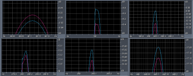
The 120Hz components differ by 0.6dB. This is not why the two waveforms are so different.
2nd order Butterworth 30Hz high pass filter is the major factor; and this is excellent simulation of sealed woofer behavior.
Impedance of sealed woofer through resonance changes dramatically. Amplifiers with different damping factors will reproduce this region quite differently. Current amplifier v voltage amplifier are examples. Choice of feedback topology can tailor amplifier behavior to a particular design.
By and large, SS designs shoot for being pure voltage source. Vast bulk of driver manufactures assume products will be driven by voltage source with significant damping factor.
Skeptical is good, but really. Take a close look at picture. All spectral components are close enough in magnitude so not to have any significant impact on differences seen between the two waveforms.
Here is composite picture of zoomed in views of each pair of spectral peaks:

The 120Hz components differ by 0.6dB. This is not why the two waveforms are so different.
2nd order Butterworth 30Hz high pass filter is the major factor; and this is excellent simulation of sealed woofer behavior.
Impedance of sealed woofer through resonance changes dramatically. Amplifiers with different damping factors will reproduce this region quite differently. Current amplifier v voltage amplifier are examples. Choice of feedback topology can tailor amplifier behavior to a particular design.
By and large, SS designs shoot for being pure voltage source. Vast bulk of driver manufactures assume products will be driven by voltage source with significant damping factor.
OK, so your claim is that two signals with different frequency component amplitudes sound different?Barleywater said:All spectral components are close enough in magnitude so not to have any significant impact on differences seen between the two waveforms
I haven't made the measurements yet but I did some more listening.
the result so far is kind of embarrassing: the 2 amps sound more similar compared to what had I initially thought. and it stroke me that the "better" one has a higher gain, which allows me to listen at higher volumes (the other one has too low a gain and with some recordings that have a higher headroom and aren't compressed, which happen to be some of the tracks I use for testing, well, you get the idea...). that, combined with a benign clipping behaviour (it's actually less powerful compared to the "worse" one) could explain much, much more than I had imagined.
the striking thing is how easy it is for one to fool oneself (in this case "one" = me), even when being aware of the factors involved (level matching and the others mentioned above).
I will get back with more impressions and data.
Last edited:
the striking thing is how easy it is for one to fool oneself (in this case "one" = me), even when being aware of the factors involved (level matching and the others mentioned above).
It's everyone. Knowing the ways the human brain can be fooled does not prevent it from being fooled, it's still a human brain.
The difference is that you're honest enough to admit it and put all your data out there. That's unfortunately rare in the audio world. All respect to you!
thanks. I've watched the behavioral patterns of some people in real life. they like to project an image of absolute confidence, which includes never admitting being wrong.It's everyone. Knowing the ways the human brain can be fooled does not prevent it from being fooled, it's still a human brain.
The difference is that you're honest enough to admit it and put all your data out there. That's unfortunately rare in the audio world. All respect to you!
I remember reading something on another forum (was it about a car problem?) a while back. one guy wrote at some point that his initial guess was wrong. some other guy respinded, no more, no less: "you're a pussy for admitting that". one of the things that I keep reminders about the credibility of Internet board discussions
Or two signals with different frequency component phases sound different?
In this case, yes.
In above synthesis I wasted time shaping waveforms to look a little more like waveforms captured from woofer system with and without linearized phase.
I readily admit that the presented waveforms have small discrepancies in amplitude spectrum. My bad. previous little experiments that I've done for myself have demonstrated that these are not the factor in perceived differences.
I've synthesized two new tracks, based on 40Hz square wave, and employed technique and methodology yielding identical spectra. The waveforms look nearly identical to the previously posted:
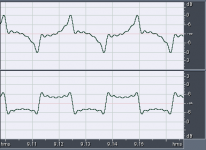
Listening impressions, and my ability to identify to two waveforms is as before.
The attached file is 20sec; 0.25sec fade in to waveform depicted above in top track for 9.5sec, 0.25sec fade out, 0.25sec fade in to more square waveform for 9.5sec, and 0.25sec fade out.
Played in continuous loop with Cool Edit in background, no visual cues exist. Periodically over several hours I put ear buds in and listen. After deciding on which waveform is which, I switch to Cool Edit screen to check my answer. In >10 trials I've missed once.
The ear buds must be well seated to get base response. I've confirmed this with measurement mic, using small piece of tubing as closed coupler that emulates ear canal. Even tiny leak leads to quick roll off below 200Hz; well sealed they reach down reasonably to <<20Hz.
Attachments
I haven't made the measurements yet but I did some more listening.
the result so far is kind of embarrassing: the 2 amps sound more similar compared to what had I initially thought. and it stroke me that the "better" one has a higher gain, which allows me to listen at higher volumes (the other one has too low a gain and with some recordings that have a higher headroom and aren't compressed, which happen to be some of the tracks I use for testing, well, you get the idea...). that, combined with a benign clipping behaviour (it's actually less powerful compared to the "worse" one) could explain much, much more than I had imagined.
the striking thing is how easy it is for one to fool oneself (in this case "one" = me), even when being aware of the factors involved (level matching and the others mentioned above).
I will get back with more impressions and data.
This description is consistent with preamp clipping when trying to drive low gain amplifier to high level.
Higher gain amplifier may also have higher input impedance compared to lower gain amplifier.
Also if pad for measuring output is insufficient, measurement preamplifier may be clipping.
Thanks for the waveform. The certainly do have a different waveform and peak value, tho RMS value is identical. However, I have a hard time telling the difference by ear. I listened on Sennheiser HD580 headphones.The attached file is 20sec; 0.25sec fade in to waveform depicted above in top track for 9.5sec, 0.25sec fade out, 0.25sec fade in to more square waveform for 9.5sec, and 0.25sec fade out
With some practice I might be able to tell them apart, but the difference isn't huge.
EDIT: Listening again, I do hear the difference. Could probably pick them blind by "fullness".
Attachments
of course, but how do you make a phase-altered waveform to have identical peaks?Different peak values will mean different distortion in the headphones. This makes it quite difficult to untangle the effect being investigated. However, at least we now have a test signal which in itself only has a phase change.
and even if peaks values are identical, the rest of the waveform matters too because it might cause the driver cone to "spend" more time in a less linear range.
Yes, the amount of interplay of all the elements in audio playback can make it a nightmare world, if you're trying to understand precisely why one thing "works" and another doesn't. So, my 'solution' is to step outside of all that, treat the whole audio setup and environment, including the power supplies in the house, as one big black box which serves only to create a certain standard of sound quality.
At any point in time the 'black box' either is good enough, or it's not - it's a Yes, or No, decision. If it's a Yes, I'm happy - and leave well enough alone. If No, then the black box is not good enough, it's got at least one weakness, somewhere, which has to be resolved. So, the black cloth is then lifted off the box, and I dive inside to track down, and resolve or circumvent the weakness ...
At any point in time the 'black box' either is good enough, or it's not - it's a Yes, or No, decision. If it's a Yes, I'm happy - and leave well enough alone. If No, then the black box is not good enough, it's got at least one weakness, somewhere, which has to be resolved. So, the black cloth is then lifted off the box, and I dive inside to track down, and resolve or circumvent the weakness ...
we do hear absolute phase
but the lack of polarity preserving standardization throughout the recording chain suggests it isn't too important
I believe I have seen a report on audible timbre variations in harmonically complex tones where the summary was that waveform amplitude envelope changes of ~1% were pretty much the threshold
but much worse isn't fatal to the listening experinece since many still buy Linkwitz-Riley XO loudspeakers - you can train to audibly identify the phase rotation through the XO frequency
basically working audio amplifier electronics don't have these problems in most the audio band - only the LF high pass could have any effect - and reducing nonlinear distortion in the DC blocking C leads to making the time constant very low anyway
but the lack of polarity preserving standardization throughout the recording chain suggests it isn't too important
Hearing – sound wave transduction to nerve impulse patterns is nonlinear
we can perceive absolute polarity because the transduction of mechanical motion to nerve impulses is asymmetric, the ion pump/gate at the base of the "hairs" on the hair cells only act when bending one way and they are all lined up along the basilar membrane in the same orientation relative to pressure wave propagation in the cochlea
the polarization change when the “hair” bends the right direction causes the release of neurotransmitters at the other end of the sensitive cells where it diffuses across the gap to trigger an impulse in the nerve fiber transmitting/processing the signal
microelectrode probing in cats show the bunching of nerve impulses at the positive? peaks of the sound wave - this absolute polarity information is largely lost above ~ 4KHz due to saturating the max impulse/recharge rate of the nerve fibers
I believe I have seen a report on audible timbre variations in harmonically complex tones where the summary was that waveform amplitude envelope changes of ~1% were pretty much the threshold
but much worse isn't fatal to the listening experinece since many still buy Linkwitz-Riley XO loudspeakers - you can train to audibly identify the phase rotation through the XO frequency
basically working audio amplifier electronics don't have these problems in most the audio band - only the LF high pass could have any effect - and reducing nonlinear distortion in the DC blocking C leads to making the time constant very low anyway
Last edited:
A key concept - a person can train themselves to audibly identify some characteristic, or aspects in sound which most others miss, or don't subjectively consider important. Then, in regard to 'live', naturally generated sound vs. a reproduction of same, most people would have no problem distinguishing the two -- so there must be some qualities that are clearly different between them - and these differences are something one can "learn" to pinpoint easily, with minimal "exertion".you can train to audibly identify the phase rotation through the XO frequency
Then, one has all the measurement tools necessary to know whether an audio system is up to scratch ...
Thanks for the waveform. The certainly do have a different waveform and peak value, tho RMS value is identical. However, I have a hard time telling the difference by ear. I listened on Sennheiser HD580 headphones.
With some practice I might be able to tell them apart, but the difference isn't huge.
EDIT: Listening again, I do hear the difference. Could probably pick them blind by "fullness".
Thanks for taking some time to listen. "Fullness" is a good descriptor. I find it easiest to tell difference when listening relaxed as if to soothing music.
Also very lucky to have friend with a number of headphones, including HD600 and HD650. Being a live sound engineer he also has Earthworks M30 microphones; a little further along the lineage of OM-1 mics I have.
I don't know why people struggle with dummy heads, everybody has one. Why would they want two? Wearing headphones, and placing microphone flat along temple with tip at edge of ear canal, very good measurements can be made:

Response on the left is from headphone.com; on the right is measurement on my head. Correlation is very good.
Headphone.com also show square wave for 50Hz and 500Hz:
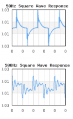
The 50Hz square wave looks much like my simulation of square wave with Butterworth high pass filtering.
Headphone.com also has similar test results for many products, including various ear buds. Here is my measurement of $10 ear bud mounted in short piece of plastic tubing to emulate ear canal; and also closed coupler measurement technique. Microphone is Earthworks OM-1.

Above is paired with HD600 results for comparison. It is easy to see that ear bud sealed to coupler rolls off low. Mechanisms at play: electronics coupling and bandwidth limiting, driver element and condenser microphone element. Even if DC coupling were used throughout the electronics, the condenser microphone capsule is vented, leading to high pass behavior.
With HD600 I also recorded swept square wave with same setup used for IR measurement. Also square wave corrected with inverse transfer function was made:
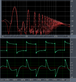
Spectra of HD600 with two signals shows that distortion is not root source of differences seen in time domain. Distortion performance of HD600 is exceptionally good.
Listening results are very similar to my results with corrected woofer system. Ear buds with 40Hz square wave retain a fair amount of the perceived difference experience with corrected HD600 headphones and with corrected woofer system.
Yes, many recordings and reproduction chains repeatedly apply an anti "fullness" filter that figures in to why recordings tend to be recognizable as such.
And a simulation of ear canal response listening to 40Hz square wave by convolution of ear bud IR with 40Hz square wave:
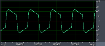
For 40Hz square wave with brick wall low pass at 500Hz, ear bud makes a good result.
Phase relationship of fundamentals to harmonics is key to much of how hearing works.
Referencing systems to state where direct comparison is possible is key to advancing understanding in this area.
mr_push_pull;
sorry for dragging thread so far off your topic.
no problem, actually I'm not very motivated to redo the measurements because I'm not sure there's any difference to explainmr_push_pull;
sorry for dragging thread so far off your topic.
no problem, actually I'm not very motivated to redo the measurements because I'm not sure there's any difference to explain
Different gain; different input impedance; different output impedance; and different high pass filtering. Very different clipping behavior.
- Status
- This old topic is closed. If you want to reopen this topic, contact a moderator using the "Report Post" button.
- Home
- General Interest
- Everything Else
- Amplifier distortion with music signal (measurements inside)
