Are you still planning on a higher supply voltage?
I'm re-thinking the use of higher supply voltage. I really don't need the extra power, the ideia was to use a regulating circuit (a simple transistor as power-follower) to filter the ripple - I've never had much luck by using only capacitors as filters. This would mean a drop in voltage of at least 5V. Using the 35V supply I would get 30V (or a little less), which might be too low. Using the 50V I would get 43-45V after the follower. To drop more seems a waste of power and more heating.
So I decided I'm going to try the circuit with a 35V supply and a simple filter capacitor bank (4 * 4700uF per rail) first. If then I find the sound "dirty" I'll use the emitter follower with the higher supply.
Thanks for the tip about the heatsinks
")
I'm re-thinking the use of higher supply voltage. I really don't need the extra power, the ideia was to use a regulating circuit (a simple transistor as power-follower) to filter the ripple - I've never had much luck by using only capacitors as filters. This would mean a drop in voltage of at least 5V. Using the 35V supply I would get 30V (or a little less), which might be too low. Using the 50V I would get 43-45V after the follower. To drop more seems a waste of power and more heating.
So I decided I'm going to try the circuit with a 35V supply and a simple filter capacitor bank (4 * 4700uF per rail) first. If then I find the sound "dirty" I'll use the emitter follower with the higher supply.
Thanks for the tip about the heatsinks
There is around 7-8V drop at the output in standard circuit, but there is allways an option.
Bellow example of double bootstrap for vas stage - as you can see the output is swinging nearly to the full rail supply.
http://www.diyaudio.com/forums/solid-state/237219-fet-hex-explendit-amplifier.html#post3530022
Last edited:
@Paulo: I experimented with power supply configurations a bit, but I have tried to keep that out of this thread, b/c it is already complicated enough.
First I tried 2x4700 per rail, later I settled on 3x4700 in a CLCRC configuration, but I am also working on a different linear power supply both for this board, and for the VSSA boards I got through the GB from LC.
The design I am using is from this thread, by MrEvil, similar to what you were describing, but the DC loss is very small, and the filtering should be just about ideal for this application.
http://www.diyaudio.com/forums/power-supplies/53359-finished-capacitance-multiplier.html
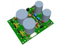
Component placement is done, layout is almost done, but some silkscreen and label issues are left. If you would like to help, or at least comment, your input would be very welcome. (a couple other people who have my boards are also helping)
@Shaan: If you would prefer to keep this out of this thread, please do not hesitate to say so.
First I tried 2x4700 per rail, later I settled on 3x4700 in a CLCRC configuration, but I am also working on a different linear power supply both for this board, and for the VSSA boards I got through the GB from LC.
The design I am using is from this thread, by MrEvil, similar to what you were describing, but the DC loss is very small, and the filtering should be just about ideal for this application.
http://www.diyaudio.com/forums/power-supplies/53359-finished-capacitance-multiplier.html
Component placement is done, layout is almost done, but some silkscreen and label issues are left. If you would like to help, or at least comment, your input would be very welcome. (a couple other people who have my boards are also helping)
@Shaan: If you would prefer to keep this out of this thread, please do not hesitate to say so.
Attachments
Last edited:


Initial testing suggests that the KSA1220AY / KSC2960AY may be a good bet.
Thanks for the tip! This could be very good alternative for VAS, especially if 1381/3503 pair proves to be impossible to find in the same hfe classification in the future. (I think that once they are sold they will not be produced anymore) If you buy some quantity ot 1220/2960 they can be used in almost any audio amp, except may be in some very high power amps. Therefore they are versatile alternative for many applications.
Thanks for the tip! This could be very good alternative for VAS, especially if 1381/3503 pair proves to be impossible to find in the same hfe classification in the future. (I think that once they are sold they will not be produced anymore) If you buy some quantity ot 1220/2960 they can be used in almost any audio amp, except may be in some very high power amps. Therefore they are versatile alternative for many applications.
I agree about the KSA1381E / KSC3503D pair, they were developed primarily as CRT drivers and since that display technology is pretty much dead so are these devices. The KSA1220AY / KSC2960AY use the same type of construction, epitaxial, and are specifically listed as an audio device on the data sheet. The basic specs look decent:
Vceo=160V for 'A' version, which is the only one in production.
Ic=1.2A continuous, 2.5A pulse (<10ms @ 50% duty)
Pd=1.2W/20W
Hfe=160-320 for 'Y' rank. My measured sample of 100 bulk packaged devices per polarity was KSA ranged from 210-320, average 258 and KSC ranged from 200-320, average 244.
Ft=175MHz (KSA) / 155MHz (KSC)
Cob=26pF (KSA) / 19pF (KSC) This is the only specification that isn't as good as many of the coveted devices of years gone by. Is this so high as to really be an issue? I doubt it and will try to make a fair comparison to see for myself.
I bought from Mouser and thought that at $0.22 each for quantity of 100, so they were decent value too. These could even function as a driver in smaller amplifiers, so likely to be reasonably versatile.
Agreed on that, it seems silly to continue to use a component which is designed for a different application, AND obsolete, when a good alternative is available.Thanks for the tip! This could be very good alternative for VAS, especially if 1381/3503 pair proves to be impossible to find in the same hfe classification in the future...
Having said that, I did call DigiKey and the KSC3503ESTU parts are still available from reputable industry sources that specialize in repair parts. Meaning, not on ebay etc. I did not get a straight answer on actual price, or minimum order.
If this other option does not pan out, and someone else is interested, I am willing to make a few more calls. Just hard to find the time during the business day right now.
In either case, has someone actually quantified the effects on this specific circuit, at least by simulation, or from previous experience?
I believe you are correct. The gate capacitance of the mosfets we are using is very high. Several hundred pF. And the drive resistor is very small. So if anything, the gate capacitance of the mosfet is likely to be an issue well before the output capacitance of the driver.Cob=26pF (KSA) / 19pF (KSC) This is the only specification that isn't as good as many of the coveted devices of years gone by. Is this so high as to really be an issue? I doubt it and will try to make a fair comparison to see for myself.
In fact, LC has reduced the gate resistor to zero ohm in GB version of the VSSA. At the same time, he did add some small caps, so to do a fair analysis of what might be best for a through-hole board, one would have to look at what he did, and likely run a couple simulations.
Cob=26pF (KSA) / 19pF (KSC) This is the only specification that isn't as good as many of the coveted devices of years gone by. Is this so high as to really be an issue? I doubt it and will try to make a fair comparison to see for myself.
I think that their Cob is low enough for any audio application including PeeCeeBee. If BD pair is good enough, this could only be much better. With BD pair the problem is not speed, good examples from good factories are declared 190MHz. The problem with BD pair is unspecified Cob which is probably high enough to cause a bit more distortion when used with Fet outputs. But 1220/2690 are excellent devices, almost as good as 2SB649A/2SD669A. They should be good enough for any audio amp as VAS/driver transistors.
Having said that, I did call DigiKey and the KSC3503ESTU parts are still available from reputable industry sources that specialize in repair parts. Meaning, not on ebay etc. I did not get a straight answer on actual price, or minimum order.
If this other option does not pan out, and someone else is interested, I am willing to make a few more calls. Just hard to find the time during the business day right now.
Pete,
When you find time (this is not urgent matter) I'd like to know if they can still be obtained in reasonable quantities.

Hi LC/Shaan,
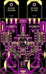
After reading the entire thread now it's time to build this PeeCeeBee, but before getting in to action i want to hear your input about this pcb.
Regards,
C1 - better avoid electrolitic capas at input, i have plenty 10uF electrolitic caps (elna, rubycon, etc etc) and must say I am not appy with them. Better is to use even 4,7uF wima MKS2 (cheap and availible everywhere).
C2 - there will be around 1,4V max at iddle so voltage rating doesnt have to be that high, also make sure You have enough room for radiatior for vas stage.
The two resistors after diodes are 10R.
Attachments
C1 - better avoid electrolitic capas at input, i have plenty 10uF electrolitic caps (elna, rubycon, etc etc) and must say I am not appy with them. Better is to use even 4,7uF wima MKS2 (cheap and availible everywhere).
C2 - there will be around 1,4V max at iddle so voltage rating doesnt have to be that high, also make sure You have enough room for radiatior for vas stage.
The two resistors after diodes are 10R.
Thanks borys... what about nonpolar caps for C1?
@wiljj78: FYI, I am using a non-polar 10uF elco. My second choice would have been a 4.7u film cap. Opinions on using the non-polarized caps vary.
Many thanks PMI...your support is really appreciated.
Regards,
I think your connection between the BC550 and BD140 is wrong. It should be Collector to Base, it isn't it?After reading the entire thread now it's time to build this PeeCeeBee, but before getting in to action i want to hear your input about this pcb.
Greets:
Tyimo
In fact, LC has reduced the gate resistor to zero ohm in GB version of the VSSA. At the same time, he did add some small caps, so to do a fair analysis of what might be best for a through-hole board, one would have to look at what he did, and likely run a couple simulations.
It seems to me that all TH boards in this thread could probably work without gate resisitors. Only Borys's pcb with two pairs of HexFets must have gate resisitors. Gate resistors are necessary with multiple Fet output pairs. If you remember the generic Hitachi schematic that I sent to you (with one pair of output transistors), there was no gate resistors. All pcbs featured in this thread are compact, with short pcb tracks and good layout with topographic placement of components that go from input to output. Therefore there should be no problems in using one output pair without gate resistors. When you repair the boards used for "antenna experiment" you can replace gate resistors with jumpers and see if bandwidth is more extended compared with resistor version and if stability is exemplary.
- Home
- Amplifiers
- Solid State
- PeeCeeBee