Why is amp1 shown playing fully 12dB lower than amp2; at 100Hz more like -18dB?
Amp2 is fairly flat up to 1kHz and then rolls off. Distortion profile shifts as 3rd harmonic passes above 1kHz. As fundamental passes above 1kHz, distortion becomes dominated by odd order. Back to the drawing board. I'm guessing amp2 is SS, and positive and negative output devices don't match well enough, or are biased enough. Somewhere a corner frequency is cut too short, and slew limiting may be occurring.
Amp1 is hummer; but indeed mostly 2nd and 3rd harmonic that maintain relationship across bandwidth. IM components can be clearly seen as side lobes to 2nd harmonic, but likely goes with amp not rejecting power supply. IM lobes following fundamental show 2nd mains harmonic too.
Complete harmonic distortion response is easy with IR by swept sine, easy to do with REW. Not to tough with Cool Edit, just need convolution plugin.
absolutely everyone who listened to both amps said that amp 1 is bass shy and I agree. and that's to name one of the obvious differences.At first glance, amp2 looks better. You say it sounds worse?
explaining that obvious difference is partially what made me pursue this.
Once upon a time I was big fan of Carver; and owned an M500 for quite some time. A good friend let me A/B with Hafler DH220. The Hafler clearly delivered more bass. In retrospect I believe it was all in the front end coupling.
When first getting into DIY I started with amplifier and built a clone of Hafler XL280 using big Exicon mosfets for output. At that point I hadn't learned IR measurement, and forged ahead with single tone and multiple tone for testing.
I've dug up some old results of 8ohm resistive loading at 85watts. 1kHz, 230ma biasing idle current:
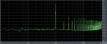
Nothing to write home about. Jacking it up to 270ma biasing idle current:
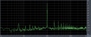
Quite respectable. Also very warm to the touch.
Pushing to 300ma biasing idle current and doing IMD with 19kHz sine with 20kHz sine:
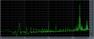
With 230ma bias the apparent noise floor all but hides the power supply spikes. Reality is it isn't noise, but a complex sea of low level IMD components.
Jfets on front end and resistor throughout were carefully matched, leaving the big differences in the characteristics of the N and P channel output fets.
During initial testing of the first driver board a grounding issue had it oscillating at 4Mhz.
Happy that great amplifiers can be built or bought, I turned my attention to building active speakers, and bought several Hafler Pro2400 amplifiers, which are essentially XL280s with balanced input boards put in front. The clone remains a ready reference.
When first getting into DIY I started with amplifier and built a clone of Hafler XL280 using big Exicon mosfets for output. At that point I hadn't learned IR measurement, and forged ahead with single tone and multiple tone for testing.
I've dug up some old results of 8ohm resistive loading at 85watts. 1kHz, 230ma biasing idle current:

Nothing to write home about. Jacking it up to 270ma biasing idle current:

Quite respectable. Also very warm to the touch.
Pushing to 300ma biasing idle current and doing IMD with 19kHz sine with 20kHz sine:

With 230ma bias the apparent noise floor all but hides the power supply spikes. Reality is it isn't noise, but a complex sea of low level IMD components.
Jfets on front end and resistor throughout were carefully matched, leaving the big differences in the characteristics of the N and P channel output fets.
During initial testing of the first driver board a grounding issue had it oscillating at 4Mhz.
Happy that great amplifiers can be built or bought, I turned my attention to building active speakers, and bought several Hafler Pro2400 amplifiers, which are essentially XL280s with balanced input boards put in front. The clone remains a ready reference.
Last edited:
you mean AC vs DC coupling, high-pass filtering...?Once upon a time I was big fan of Carver; and owned an M500 for quite some time. A good friend let me A/B with Hafler DH220. The Hafler clearly delivered more bass. In retrospect I believe it was all in the front end coupling.
Bass shy but clearly better? In what way better?absolutely everyone who listened to both amps said that amp 1 is bass shy and I agree.
Uh, yeah. Probably better to start all over again.Now we're thoroughly confused ...
To do this right, get fresh listening impressions of both amps. List those here. Then proceed on to new, level matched measurements.
Thanks.
it was actually only a matter of denomination, you'd have to agree that "amp 1" and "amp 2" are labels that are easily mistaken.
but I know for a fact which measurement is which.
I'll redo level-matched measurements if you like but really don't expect something very different there.
as for sound... everyone who listened to both amps, after listening to 2 said things like "I would call the sound precise but it doesn't go low" or "there's something wrong at the ends of the spectrum" which mirrored my sensation. and I never told them before what they should be hearing, Nordost-style (google for Nordost + breakthrough and you'll find a vid where the Nordost guys tell the audience what they will be hearing). with amp 1 the same people agreed that those issues are pretty much solved.
Last edited:
I'll redo the measurements but don't hold your breath, you won't see anything very different except a lower noise floor 
the confusion rises from the fact that I didn't assign more meaningful names to the said amps, which is error-prone.
hint: the fact that one of those amps has no mains-related components is because it uses a SMPS, while the other one uses a linear supply. pretty hard to mistake that. and I should know which is that one because I've used it for quite a few years
Last edited:
so we have:
amp 1 - pretty high distortion but practically frequency-independent and mains-related components
amp 2 - lower distortion, no mains-related components but distortion varies with frequency (harmonics distribution is different too) and rises at the top end
to me and everyone else who listened, amp 1 sounds clearly better.
I'm going to beat a dead horse and suggest you read Crowhurst's "Some Defects in Amplifier Performance Not Covered by Standard Specifications," Journal of the Audio Engineering Society, October 1957, pp. 195 to 201.
It's the grand-pappy paper on this problem.
There is an earlier paper by Shorter (1950) "The influence of High-Order Products in Non-Linear Distortion," in Electrical Engineering, April 1950, pp. 152-153. which I've not read yet
Mr Hoffman has already described some better ways of getting to the actual distortion products - there's a bunch of papers on how to do this too.
you mean AC vs DC coupling, high-pass filtering...?
AC coupling as high pass filter as typically employed, even as simple first order filter with corner at 6Hz has loads of phase shift <150Hz, even though response will measure very flat >20Hz. Example, Butterworth 1st order 6Hz HP filter:
Spectrum of filter:

Tops of 100Hz square wave with filter applied:
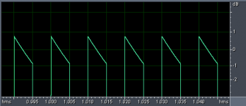
Tops of 40Hz square wave with filter applied:
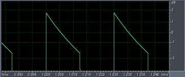
If this is all amplifier path is doing to signal, then all transients are smeared. Then of course the drivers twist this even further.
hint: the fact that one of those amps has no mains-related components is because it uses a SMPS, while the other one uses a linear supply. pretty hard to mistake that. and I should know which is that one because I've used it for quite a few years
Why hints? What are the two amplifiers?
Mains related components are clearly visible for both amplifiers in posted videos. Cool Edit in playback typically limits size of FFT, partly based on processing power. Your videos look to be using FFT of about 8k, based on width of peaks. This clearly limits resolution of mains frequency type signals.
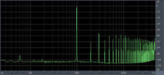
My post of 230ma conditions barely shows 60Hz with FFT 65k, but it is there; selecting a larger window and using "scan" feature to average FFT window over time suppresses noise with random phase, and out it pops:
Old Hafler amps use simple linear supply. Big, low ESR reservoir caps, and 0.01 uf cap across mains at diode bridge. PSR is achieved with fully symmetrical amplifier circuit.
Hafler had nothing magical to hide. User manuals supply complete schematics and parts lists. This is partly why I chose to clone XL280 for experience in building an amplifier.
I applaud your efforts in trying to figure out why two amplifiers clearly sound different. Measurements will let you pinpoint this.
Distortion is a tough nut; plenty of studies show that some types of distortion are of no concern to listeners. Some on forum point to tiny levels of switching noise/distortion to be highly audible. I never got around to listening exercise of XL280 clone with different bias settings, although clearly the further it is pushed into class A, the better looking the plots look. This is all in the switching region.
If this is all amplifier path is doing to signal, then all transients are smeared.
Really? That's not what your pictures show.
Does anyone have data demonstrating the audibility of a 1st order highpass with fo below 10Hz?
- Status
- This old topic is closed. If you want to reopen this topic, contact a moderator using the "Report Post" button.
- Home
- General Interest
- Everything Else
- Amplifier distortion with music signal (measurements inside)