put this into your woofer
and hook it up to a pair of these to build your own mfb.
An externally hosted image should be here but it was not working when we last tested it.
and hook it up to a pair of these to build your own mfb.
An externally hosted image should be here but it was not working when we last tested it.
Ippo: Your chip looks ... erm ... damaged.
bute nice build, btw")
If you are refering to the area around the lettering on the ic, I think it is a shadow and some stray thermal compound.....hopefully.
Yes that is correct some thermal compound on and on the side of the chip... I didn't clean it up after mounting it.
It's not damaged and plays nicely!
Though I'm trying to put a Truepath together now to compare.
My First Build
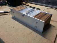
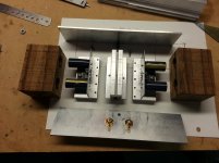
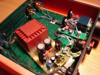
Hello! I just finished building one of the excellent Audiosector LM3875 kits by Peter Daniel. I was inspired by Peter's Patek design, so I borrowed heavily from that design for my amp.
The chassis is made from scrap aluminum heat sinks I found at a local electronic parts supplier and a couple of pieces of flat aluminum from Home Depot. I bought inexpensive Zebra wood turning blocks I found on the Internet for the end caps. Like Peter's Patek design, I drilled my wood blocks to fit over the capacitors to keep the footprint small. All I have to do to complete my project is to build a case for the external power supply...
The result is a cool looking amp that sounds great and runs cool!
Attachments
Hi Guys,
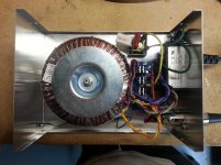
I have recently finished my LM3886 chipamp using Brian GT boards. It's a standard build in a surplus equipment case. The heat sink is also a surplus purchase for £0.50! Originally I was going to build the amp as dual mono but then found the case which isn't big enough for two transformers. I'm not sure about the front panel which is 0.3mm carbon fibre/kevlar sheet over the original front which has lots of unwanted holes in it. The blue LED power indicator shines through the sheet. I may still get a front panel made by Schaeffer AG.
I'm happy with the sound and the heat sink gets hardly warm.
Tony
Attachments
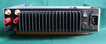
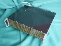
The Kevlar/Carbon has a snazzy look.
You have made good use of twisting.
Clean the top and bottom joints of the chassis so that they become electrically conducting. A non conducting seem/gap lets in RF. I'm still reading H.Ott.
Do you have Thermal compound in the sink to chassis interface?
You have made good use of twisting.
Clean the top and bottom joints of the chassis so that they become electrically conducting. A non conducting seem/gap lets in RF. I'm still reading H.Ott.
Do you have Thermal compound in the sink to chassis interface?
Hi Andrew,
The back of the heat sink was checked for flatness with engineers blue and fine wet and dry on a thick piece of plate glass. The same with the back panel. The two were then pulled together with 16 cs M4 screws with thermal paste between. There couldn't be a more intimate thermal contact between the two. At the planning stage I did think about cutting a hole in the panel so that the devices bolted directly onto the heat sink but decided not to. Note also the aluminium strip under the heads of the bolts securing the packages which I believe allows higher torqueing of the fixing bolts and thus improves the thermal interface between the packages and the panel.
Tony
Hi Andrew,
The back of the heat sink was checked for flatness with engineers blue and fine wet and dry on a thick piece of plate glass.
Nice to know I'm not the only one who does this...
Heatsinks are never "flat" except for those nice ground surfaces from Conrad Heatsinks in Aus.
Levies tubby: neat looking build.
Theres like one pic per page, too much talk.
Hello! I just finished building one of the excellent Audiosector LM3875 kits by Peter Daniel. I was inspired by Peter's Patek design, so I borrowed heavily from that design for my amp.
The chassis is made from scrap aluminum heat sinks I found at a local electronic parts supplier and a couple of pieces of flat aluminum from Home Depot. I bought inexpensive Zebra wood turning blocks I found on the Internet for the end caps. Like Peter's Patek design, I drilled my wood blocks to fit over the capacitors to keep the footprint small. All I have to do to complete my project is to build a case for the external power supply...
The result is a cool looking amp that sounds great and runs cool!
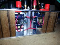
Nice amp! I would change those 10uf capacitors in the power supply for at least 6800uf. I build those kits long time ago and I try many caps in the power supply and I found that those 10uf caps are JOKES!!! When I changed them to 10000uf I got a huge improvement in the sound (bass). just give it a try.
Nice amp! I would change those 10uf capacitors in the power supply for at least 6800uf. I build those kits long time ago and I try many caps in the power supply and I found that those 10uf caps are JOKES!!! When I changed them to 10000uf I got a huge improvement in the sound (bass). just give it a try.
Lanchile - Thanks! Did you use the snubber parts with the 10000uf caps, or did you simply replace the 10uf caps for 10000uf caps?

Absolutely right, mrWagner!
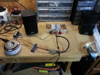
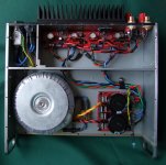
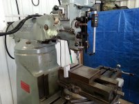
Here are two more pictures of my Gainclone amp chassis build. I used a friend's Bridgeport milling machine with his help to build that center section and trim the rest of it to size. Also, here's the PSU in question all boxed up in a cheap enclosure I found locally.
Here are two more pictures of my Gainclone amp chassis build. I used a friend's Bridgeport milling machine with his help to build that center section and trim the rest of it to size. Also, here's the PSU in question all boxed up in a cheap enclosure I found locally.
Attachments
Lanchile - Thanks! Did you use the snubber parts with the 10000uf caps, or did you simply replace the 10uf caps for 10000uf caps?
I just replaced the 10uf for 10000uf. you will hear the big difference. the bass came alive. I do not know why Peter chose these small caps for the power supply
. some people say with small caps the sound is much better...and I say it is wrong!!! a real power supply should have enough juice as reserve for the big demands. I have never seen a "real" amplifier with a 10uf capacitors as power supply...to me that is a joke!Me neither ... nor you.
The *real* filter caps (and called so in the kit literature) are the
In fact, the 10uF caps are so unimportant that they can be omitted:
Sorry for chiming in talking PSU in a picture thread, but the above post makes ridiculous claims.
And since I should post some chip amp picture to keep the spirit of the thread, here's mine:
"Fahey Callejero 30"
30W biamplified Instrument amp.
Bridged TDA2005 driving a 3.2 ohms low/mids speaker and a TDA2003 driving a 4 ohms LeSon tweeter.
Fed from a 16V PSU when plugged into 220V (which also charges the battery) and 12,6 VDC when fed from its internal 12V 7AH alarm type battery.
It also includes a switching +/-15V inverter to feed the preamp Op Amps and has an optional 9V supply output to feed Musician's pedals if playing in the street/beach/subway station/etc.:


The *real* filter caps (and called so in the kit literature) are the
which in my book are too small, but making a big fuss claiming "that PSU uses 10uF filter caps" as if they were the only ones, is ridiculous.4 x 1500uF 50v Panasonic FC Capacitors
In fact, the 10uF caps are so unimportant that they can be omitted:
optional two small capacitors (10uF) which you may use, but they are not really required.
Sorry for chiming in talking PSU in a picture thread, but the above post makes ridiculous claims.
And since I should post some chip amp picture to keep the spirit of the thread, here's mine:
"Fahey Callejero 30"
30W biamplified Instrument amp.
Bridged TDA2005 driving a 3.2 ohms low/mids speaker and a TDA2003 driving a 4 ohms LeSon tweeter.
Fed from a 16V PSU when plugged into 220V (which also charges the battery) and 12,6 VDC when fed from its internal 12V 7AH alarm type battery.
It also includes a switching +/-15V inverter to feed the preamp Op Amps and has an optional 9V supply output to feed Musician's pedals if playing in the street/beach/subway station/etc.:
My headphone amplifier based on BUF634T, the PCB is designed as dual mono but I am using it as stereo. I the near future I will replace this LM317/337 regulator with tracking preregulator based on Linear technology LT's, that is why the wiring isn't done so well.
For the casing I have used old PCBs and two aluminum profiles from other casing. RCAs and headphone jack are from Neutrik, volume button and rhodium IEC are from ebay. I really like it visualy and sonicaly, sound is very neutral with lots of dynamics and really goes well with mine HD598.
Best Regards,
Ales
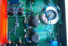
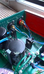
Recently I have upgraded my PSU in this headamp. Changed those LM317/337 regulators with 2x LT1085, added bigger capacitors and toroidal transformer. Now I have even better sound
First picture is from old setup and the other two are from new one!
Best Regards,
Ales
Attachments
Does anyone have a part number for those nice heatsinks you guys use?
I always use this company, you can get ANY size you want and they are very precise in their measurements.Extruded Aluminum Heatsinks from HeatSinkUSA
- Home
- Amplifiers
- Chip Amps
- Chip Amp Photo Gallery