Test Of AuraSound 2" Driver As Synergy Midrange
I put together a small test of the AuraSound 2" driver for use in a Synergy Horn. After some trial and error I ended up with a 12mm thick port baffle and an 18mm thick driver mounting baffle. These are common thicknesses for baltic birch plywood. The port length and chamber volume had to be a little smaller than predicted to get the desired response. The hole saws are 1-7/8" (48mm) and 3/4" (19mm) diameter. The roundover bit is 1/8" radius (3mm). I sealed around the driver and the cap with hot melt glue. Silicone RTV gives off acid when it cures and solvent based glue vapors may affect the driver adhesives.
Here's a series of photos of the build and measurement:


Here's the frequency response measurement. It is pretty much what is needed to compensate for the beginning portion of the 1/4 wave horn throat reflection notch and extend the upper midrange frequency response.

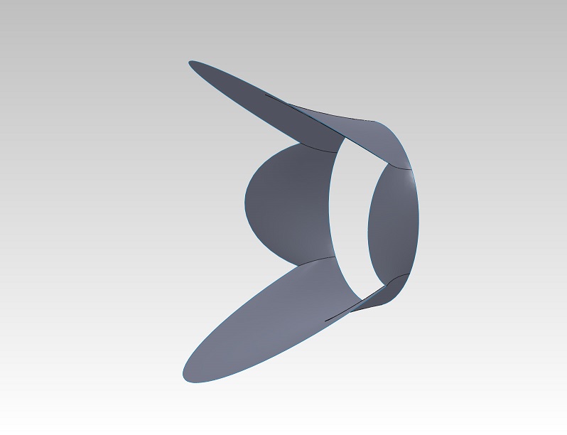
Here is what the design looks like now in a cross section through two of the drivers.

I put together a small test of the AuraSound 2" driver for use in a Synergy Horn. After some trial and error I ended up with a 12mm thick port baffle and an 18mm thick driver mounting baffle. These are common thicknesses for baltic birch plywood. The port length and chamber volume had to be a little smaller than predicted to get the desired response. The hole saws are 1-7/8" (48mm) and 3/4" (19mm) diameter. The roundover bit is 1/8" radius (3mm). I sealed around the driver and the cap with hot melt glue. Silicone RTV gives off acid when it cures and solvent based glue vapors may affect the driver adhesives.
Here's a series of photos of the build and measurement:
Here's the frequency response measurement. It is pretty much what is needed to compensate for the beginning portion of the 1/4 wave horn throat reflection notch and extend the upper midrange frequency response.
Here is what the design looks like now in a cross section through two of the drivers.
Attachments


AuraSound Synergy Throat Adapter
Mounting the compression driver in close is difficult. I finally figured out an easy way to do it. After installing two smooth threaded 6mm studs into the driver mounting holes, just slide it into place with guide holes on the horn assembly. The studs will support the driver weight. Double stick foam permanent mounting tape will provide the seal and hold the driver in place (scrape the foam gasket off the driver face first). Removing the driver should never be necessary as the driver diaphragm is replaceable from the rear. I'm sure I can get it off with a thin sharp putty knife if I ever need to.


The critically shaped throat adapter (Quadratic Waveguide Profile) is intended to be made in a 3D printer. I've attached a zipped .stl file that anyone can use to have them made. With a wall thickness of a few millimeters the part can be fabricated with a honeycomb core to save time, material and cost. The part is 29 x 72 x 112 mm overall.

I guess I'm ready to have the throat adapters made now.
Mounting the compression driver in close is difficult. I finally figured out an easy way to do it. After installing two smooth threaded 6mm studs into the driver mounting holes, just slide it into place with guide holes on the horn assembly. The studs will support the driver weight. Double stick foam permanent mounting tape will provide the seal and hold the driver in place (scrape the foam gasket off the driver face first). Removing the driver should never be necessary as the driver diaphragm is replaceable from the rear. I'm sure I can get it off with a thin sharp putty knife if I ever need to.
The critically shaped throat adapter (Quadratic Waveguide Profile) is intended to be made in a 3D printer. I've attached a zipped .stl file that anyone can use to have them made. With a wall thickness of a few millimeters the part can be fabricated with a honeycomb core to save time, material and cost. The part is 29 x 72 x 112 mm overall.
I guess I'm ready to have the throat adapters made now.
Attachments


Last edited:
Any reason the throat adapter cant be omitted? I was thinking the walls of the horn could just continue down and be shaped later on by hand.
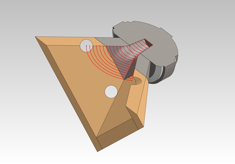
I'm just using a 3D printer because it is easy for me. You can try it by hand. The inside surface contour looks like this:
Just be sure to "focus" the horizontal and vertical walls of the horn on the inside to a point. Then truncate the horn at the same place I did (see earlier posts). Do not make a 0.7" square opening and try to "round" it to this shape, it won't work. Before hand finishing, the throat should have the same proportions as the horn mouth, just smaller.
Last edited:
Do not make a 0.7" square opening and try to "round" it to this shape, it won't work.
Huh? This is how I've made all my horn throats. For a 1" driver I build my conical horn shell with a 0.7" square throat and then open it up with a 7/8" Forstner bit on a drill press. Final shaping is done with a 1/2" dowel rod wrapped with sandpaper. This method has worked everytime for me.
Huh? This is how I've made all my horn throats. For a 1" driver I build my conical horn shell with a 0.7" square throat and then open it up with a 7/8" Forstner bit on a drill press. Final shaping is done with a 1/2" dowel rod wrapped with sandpaper. This method has worked everytime for me.
I'm not saying you can't make any hand finished shape you want. I have designed a Quadratic Throat Waveguide as invented by Hughes.
Quadratic Throat Waveguide
If you are changing the horn aspect ratio as the walls converge, the horn then has astigmatism as described in the referenced document.
If you are changing the horn aspect ratio as the walls converge, the horn then has astigmatism as described in the referenced document.
Is it audible?
From your link:I'm not saying you can't make any hand finished shape you want. I have designed a Quadratic Throat Waveguide as invented by Hughes.
Quadratic Throat Waveguide
If you are changing the horn aspect ratio as the walls converge, the horn then has astigmatism as described in the referenced document.
"The Problems With Most Current Constant-Beamwidth Horn Designs:
Most current popular horn designs share a common set of problems:
1. The ellipsoidal wavefront astigmatism caused by different horizontal and vertical apparent apices, which, by definition, is a characteristic of slot-loaded horn bells."
The astigmatic problems are with slot-loaded horns, not with the Hughes throat, which can be easily be approximated as JLH described without the need of computer printing.
Not that I wouldn't do it with a printer if I had one, but a half hour of throat sanding is no big deal compared to all the rest of the cabinet details.
From your link:
"The Problems With Most Current Constant-Beamwidth Horn Designs:
Most current popular horn designs share a common set of problems:
1. The ellipsoidal wavefront astigmatism caused by different horizontal and vertical apparent apices, which, by definition, is a characteristic of slot-loaded horn bells."
The astigmatic problems are with slot-loaded horns, not with the Hughes throat, which can be easily be approximated as JLH described without the need of computer printing.
The astigmatism is not caused by the slot loading, it is per Hughes, "caused by different horizontal and vertical apparent apices". This does occur in slot loaded horns and others.
Here is an illustration of the problem:
It is easy to see in this 90 x 40 conical horn image that the side and top walls have different apices which will cause astigmatism in the radiated wave pattern of the horn. This happens because the walls are shifted along the horn axis to make a square throat. If the horn walls make a rectangular throat like the horn mouth, they meet at the same point with no astigmatism in the horn.
In my case, the Quadratic Throat is a transition from a rectangular horn to a round compression driver. Square throats are correct when the horn mouth is square.
Can you hear the benefits of a Quadratic Throat Waveguide?
From testing by Hughes: "Where the Quadratic-Throat Waveguide® really outperformed the standard constant-beamwidth coverage horn was in harmonic distortion. At several power levels and across all frequencies, the 2nd harmonic distortion level was almost uniformly 3 to 4 dB better. And finally, the 3rd harmonic distortion, the most irritating for the listener, averaged about 9 dB better than the conventional design. This is an easily discernable sound quality difference over the older designs."
That is enough of a potential benefit to me to be careful to produce accurate horn wall and throat geometry designed to generate a spherical wave front with minimal distortion.
Attachments


i don't see any quadratic thingy on this?
I hope not. It is patented and can not be used by Danley Sound or other professionals without permission.
Quadratic Waveguide Patent: Patent Link
An important detail I have included in the design (at least important per Earl Geddes) is to match the horn throat angle to the flare angle of the compression driver exit.
Last edited:
I put together a small test of the AuraSound 2" driver for use in a Synergy Horn. After some trial and error I ended up with a 12mm thick port baffle and an 18mm thick driver mounting baffle. These are common thicknesses for baltic birch plywood. The port length and chamber volume had to be a little smaller than predicted to get the desired response. The hole saws are 1-7/8" (48mm) and 3/4" (19mm) diameter. The roundover bit is 1/8" radius (3mm). I sealed around the driver and the cap with hot melt glue. Silicone RTV gives off acid when it cures and solvent based glue vapors may affect the driver adhesives.
Here's a series of photos of the build and measurement:
Here's the frequency response measurement. It is pretty much what is needed to compensate for the beginning portion of the 1/4 wave horn throat reflection notch and extend the upper midrange frequency response.
Here is what the design looks like now in a cross section through two of the drivers.
Aloha Hulkss.
You doing such a nice job with all the attention to details and... everything... I just don't get why you're using middrivers with aluminum cones? There are a lot of nice mids with paper-cones to choose from and they are really sound different from those Aura's. In the end of project, consuming the cost of all materials, components and time spend on it, it's not worse to use something that you probably want to replace in a future for the better one. It's not about the measurement, it's all about a sound, right? Please don't consider it as a offence, wish you the best.
just my IMHO.
Thank you for sharing with us such a nice project.
Hulkss!
I would also like to give my appreciation to you regarding the details of your work.
But I also agree with grec13 on the metal cones. We could be wrong though!
/Thomas
I think the principle issue of metal cones, is that they have nasty break-up modes, as compared to materials with better damping properties, e.g., paper. I've had speakers made with Seas magnesium cone drivers which sounded very nice, as the breakup was managed in the crossover to keep the driver in its optimum band pass. That task is even easier here, due to the inherent bandpass nature of the enclosure. Used carefully, metal cone drivers can have lower distortion than more compliant materials.
Sheldon
Sheldon
I agree that metalic cone drivers (The Aurasound diaphragm is titanium) can sound harsh due to break-up modes in the diaphragm. That is why I am using a high frequency 1" compression driver with a polyimide cone (B&C DE 250).
In the case of this midrange application, the driver is covering only two octaves: 300 to 600 Hz and 600 to 1200 Hz. With that in mind, I selected a small but powerful driver with the the purpose of operating it in the range of true piston motion.
A key feature of the AuraSound driver is the perimeter voice coil, the same as a compression driver. This drives the cone only from the outer edge to minimize bending forces in the cone:


Keep in mind this driver it tiny. The cone is the same size as the B&C compression driver diaphragm. Any cone break-up is well above the range I am using it in. In addition the band-pass nature of the midrange port further reduces any unwanted high frequency output.
Even though this driver is tiny, four of them will still easily reach 120 dB output in the horn. This is limited by port air velocity at 300 Hz, not the driver (ports are 3/4" diameter).
If you are concerned about the perceived sound quality of the AuraSound 2" driver look here: Pluto Loudspeaker
In the case of this midrange application, the driver is covering only two octaves: 300 to 600 Hz and 600 to 1200 Hz. With that in mind, I selected a small but powerful driver with the the purpose of operating it in the range of true piston motion.
A key feature of the AuraSound driver is the perimeter voice coil, the same as a compression driver. This drives the cone only from the outer edge to minimize bending forces in the cone:
Keep in mind this driver it tiny. The cone is the same size as the B&C compression driver diaphragm. Any cone break-up is well above the range I am using it in. In addition the band-pass nature of the midrange port further reduces any unwanted high frequency output.
Even though this driver is tiny, four of them will still easily reach 120 dB output in the horn. This is limited by port air velocity at 300 Hz, not the driver (ports are 3/4" diameter).
If you are concerned about the perceived sound quality of the AuraSound 2" driver look here: Pluto Loudspeaker
If I'm not mistaken, this thread started seven years ago when Puggie was following my thread on audiogroupforum, and came over to diyaudio to figure out if the drivers I was using were a good choice ")
And ironically, they were the very same drivers you are using
Twelve Inch Woofers In My Dash - CARSOUND.COM Forum
And ironically, they were the very same drivers you are using
Twelve Inch Woofers In My Dash - CARSOUND.COM Forum
And ironically, they were the very same drivers you are using
Yes, I noticed when I was searching for drivers, you had given these little guys a try. They have not changed much over the years. Only the the Fs spec has changed from 200 to 250 Hz. That is where I measured it to be.
Yes, I noticed when I was searching for drivers, you had given these little guys a try. They have not changed much over the years. Only the the Fs spec has changed from 200 to 250 Hz. That is where I measured it to be.
Over the years I've come to the conclusion that geometry is more important than Thiele Small specs when it comes to the midranges in a Unity horn. I've posted some pictures on this thread that go into exhausting detail on why this is. But basically I now believe that you can make a lot of drivers work that wouldn't *appear* to work based purely on the Thiele Small parameters.
And conversely, there are some big drivers that have the right thiele small parameters that *won't* work because you can't get them physically close enough to the compression driver. Particularly when you consider the pathlength from one edge of the driver cone to the other. (IE, you might be able to get the driver close, but the pathlengh disparity from one edge of the cone to the other is a problem.)
Long story short: I probably could've made the Whispers work if I'd mounted them face down on the horn, instead of putting them in those weird bandpass enclosures:

^^^ weird bandpass enclosures feeding my first Unity horn via plastic tubing. Pathlength nightmare
^^^Over the years I've come to the conclusion that geometry is more important than Thiele Small specs when it comes to the midranges in a Unity horn.....there are some big drivers that have the right thiele small parameters that *won't* work because you can't get them physically close enough to the compression driver......you might be able to get the driver close, but the pathlengh disparity from one edge of the cone to the other is a problem.
That is a big reason why I have arrived where I am with the design I am developing. Based on the results and issues posted by many others, I believe that the geometry is critical. This includes the midrange ports, the port geometry, the port location, and the horn throat for the compression driver.
I also believe that port offset combined with the extremely high compression ratio that results with larger midrange drivers can be problematic. Especially when the driver cones were not designed for high compression.
- Home
- Loudspeakers
- Multi-Way
- Suitable midrange cone, for bandpass mid in Unity horn.