My voltage show 58v output
67.7k so it's ok
3-4VDC when its energized in the circuit.
Thanks good to know. This is the same w/ dummy load or my circuit attached?
My voltage show 58v output
67.7k so it's ok
Look if you got any structural damage also, like a broken via or an intermittent sense/force connection/wire, broken isolation etc.
Broken what?
Broken what?
Isolation pad broken or screw making contact to main sink.
It was in the my circuit. I found after that I had swapped the 1.8 ohm r6 with the 1.8k r8.
So I changed out q1, q2 and q3, q4,5,6 also the zeners I still have the same results. I can set the mV's but no voltage traveling all the way thru. I have 330vdc should see 310vdc coming out. Oh, currently it seems to pull my power supply down to 285vdc
So I changed out q1, q2 and q3, q4,5,6 also the zeners I still have the same results. I can set the mV's but no voltage traveling all the way thru. I have 330vdc should see 310vdc coming out. Oh, currently it seems to pull my power supply down to 285vdc
Isolation pad broken or screw making contact to main sink.
Those are ok.
Salas,
I think your builders would benefit from an instruction set showing how to build and test the HV in easy stages.
LV AC into the CCS stage with a simple shorted output and no components stuffed for the regulator part.
The builder can then experiment with the current setting resistor and prove that the CCS is working properly.
Then add on the regulator components, but with a LOW VOLTAGE setting resistor/reference tacked on so that it is easy to replace with the final value. Test the CCS+REG using LV AC.
Finally go to HV AC and final Voltage Setting Reference and test with an HV dummy load.
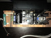
That would be alright for understanding the circuit, put it to pace without HV hazards, experimenting etc. This one we try find why there is no VGS on the output Mosfet was a a working one that failed or one that never worked though I am not sure yet. Visually is OK for components stuffing.
R10 shows 68k installed on the board - r9 shows 43.5k installed also, should I pull a leg up and retest? Or replace?
Voltage trimmer was replaced does minimal was tested before install and did work, can adjust mV's set to 393 what I need .19 + .20mA.
I think your talking about the current trimmer here. How about the voltage trimmer, is it working?
When I happend to short the CSS sink with Vin the IRF, 2SK117 and D1 putted their ski's in the weather.
Last edited:
I think your talking about the current trimmer here. How about the voltage trimmer, is it working?
When I happend to short the CSS sink with Vin the IRF, 2SK117 and D1 putted their ski's in the weather.
I replaced trimmer for the voltage it was tested off the circuit and worked
Salas,
I think your builders would benefit from an instruction set showing how to build and test the HV in easy stages.
LV AC into the CCS stage with a simple shorted output and no components stuffed for the regulator part.
The builder can then experiment with the current setting resistor and prove that the CCS is working properly.
Then add on the regulator components, but with a LOW VOLTAGE setting resistor/reference tacked on so that it is easy to replace with the final value. Test the CCS+REG using LV AC.
Finally go to HV AC and final Voltage Setting Reference and test with an HV dummy load.
I agree!
")
- Home
- Amplifiers
- Power Supplies
- Simplistic MosFET HV Shunt Regs