Simple output stage inclusive Miller compensation as recommended by Cherry has to possess a single pole minor loop response up to and beyond minor loop gain frequency otherwise it wouldn't be stable.Hi jcx,
Probably you have overlooked above post, but I would like to get an answer from you, please.
Cheers,
E.
Wat are OIC amps?
I thought I was keeping up wid dem evil TLAs but I'm fast falling behind cos the rate of advancing polysyllabicity.
Then there's dem new (possibly pseudo) guru names like Middlebrook, Tian etc to go with the Holy Baxandall, Cherry, Cordell, Self et al
OIC = Output Inclusive Compensation. Avoids debates about who actually first came up with it.
Best wishes
David
OIC = Output Inclusive Compensation. Avoids debates about who actually first came up with it.
Next step is to define IOIC = Input Output Inclusive Compensation. Also known as lead compensation
.Next step is to define IOIC = Input Output Inclusive Compensation.
Since Input Inclusive Compensation seems to be better and Output Inclusive has promise that does seem the obvious conclusion, doesn't it?
If we take this seriously then the problem becomes how to transition all the networks to maintain stability as the frequency increases.
TMC is just the simplest example of this kind of approach. And as we have seen, even that is not so simple to understand.
I try Bode style admittance matrix analysis, as used by Cherry, but it's hard work. Any one else have any developments on this?
Best wishes
David
Nth order systems
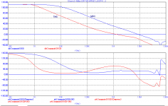
So far I got little response on my question. Presumably, most people had a feeling that it is a catch question. Indeed it is so. Have a look at the following picture, which depicts the gain and phase response of a TMC respectively an OIC amplifier. The one side of gain probe was put at the output, the other side connected to the FB resistor and compensation stuff (TMC resistor respectively Cdom). The TMC amp, as expected, shows a roll-off of near 12dB/oct, which indicates it's a 2nd order system (nothing new under the sun). The OIC amp on the other hand, which seems to have a 1st order compensation, also rolls-off with near 12dB/oct.
So we have the funny situation that the one amplifier with a 2nd order compensation scheme shows (basically) the same behavior as an amp with a 1st order compensation. Shouldn't we call all amplifiers a >1 order system, instead of only TMC or TPC amps? But if we reject this idea, then we could call, for the same reason, a TMC amp a 1st order system.
Cheers,
E.
NB: The amp was a blameless one with a cascoded TIS.
When you say that you mean the system then the answer is "it depends".
Since OIC amplifiers are notorious for instability some presumably have more than two poles.
Even Miller compensated amps have second order behaviour, just not where we normally care.
Best wishes
David
So far I got little response on my question. Presumably, most people had a feeling that it is a catch question. Indeed it is so. Have a look at the following picture, which depicts the gain and phase response of a TMC respectively an OIC amplifier. The one side of gain probe was put at the output, the other side connected to the FB resistor and compensation stuff (TMC resistor respectively Cdom). The TMC amp, as expected, shows a roll-off of near 12dB/oct, which indicates it's a 2nd order system (nothing new under the sun). The OIC amp on the other hand, which seems to have a 1st order compensation, also rolls-off with near 12dB/oct.
So we have the funny situation that the one amplifier with a 2nd order compensation scheme shows (basically) the same behavior as an amp with a 1st order compensation. Shouldn't we call all amplifiers a >1 order system, instead of only TMC or TPC amps? But if we reject this idea, then we could call, for the same reason, a TMC amp a 1st order system.
Cheers,
E.
NB: The amp was a blameless one with a cascoded TIS.
Attachments
Last edited:
Hi Edmond,
As I am not getting any answer on my question about TMC simulation http://www.diyaudio.com/forums/soli...-self-wants-your-opinions-79.html#post3466242, and for me, your TMC simulation, according to your description, was done in the same way, I would like to get your oppinion if my simulation is good enough to evaluate TMC amp?
Regards Damir
Hi Edmond,
As I am not getting any answer on my question about TMC simulation http://www.diyaudio.com/forums/soli...-self-wants-your-opinions-79.html#post3466242, and for me, your TMC simulation, according to your description, was done in the same way, I would like to get your oppinion if my simulation is good enough to evaluate TMC amp?
Regards Damir
Dadod
I'm wondering if you have ever read the answers you have got so far, both at Andy's place by me and syn08 and at this place by eg. jcx.
First of foremost, Edmond (jcx, syn08 and I) use Tian probe, not a simple probe.
So the first thing you should do is is using a Tian probe, maybe it would be easier to see what you are doing and analyse your results.
Secondly you don't show what you have in front and after the amp (LPF a.s.o). (in my opinion, everything in front and after the amp should be removed when you do an AC analysis (everybody don't agree about this)). In my opinion local oscillation may not show up if you strangle the analysis by external components. (The same with transient analysis of clipping and square wave, (if ringing shows up, it's better to analyse it then hiding it)
If you look at Edmond's site you will see where he puts the probe for analysing the different loops, both the whole amp and the inner loops.
S
Hi Stein,
Thank you for (partly) answering Damir's question.
Hi Damir,
Regarding the location of the gain probe, there ain't no single correct location. It all depends on what you want to know. It measures what it measures. So, when publishing results, always tell where you have put the gain probe and also whether you have excluded unwanted interactions from other parts of the circuits, by means of a large cap or so.
Cheers,
E.
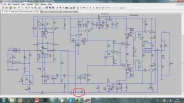
Sorry if my simulation picture was not clear enogh. Yes, I could use Tian probe, but just to show how to get a TMC amp Loop Gain, were TMC second order slope is shown, simple voltage probe is good enough.
Here is whole simulation picture with the probe position encircled.
BR Damir
Here is whole simulation picture with the probe position encircled.
BR Damir
Attachments
Okay, that's one way to do it, in particular if you want to prove it's an 2nd order system.
The other way, i.e. R30 directly connected to the output, 'proves' it's a 1st order system (which it isn't), though it nicely explains why you don't get overshoot. I think you should simulate both loops and both of them should have sufficient phase and gain margin. Also check the Miller loop itself (put the gain probe between Q15 & Q12, for example), so that makes three of them.
Cheers,
E.
Okay, that's one way to do it, in particular if you want to prove it's an 2nd order system.
The other way, i.e. R30 directly connected to the output, 'proves' it's a 1st order system (which it isn't), though it nicely explains why you don't get overshoot. I think you should simulate both loops and both of them should have sufficient phase and gain margin. Also check the Miller loop itself (put the gain probe between Q15 & Q12, for example), so that makes three of them.
Cheers,
E.
Thanks Edmond,
Yes I simulate both way, R30 connected to the output, but this loop gain shows to optimistic phase margin, I think, and as you said, 1st order system which it isn't. And don't need to prove that it is 2nd order system, but to see what phase and gain margin I could have.
I never saw in this thread TMC simulation in the way that TMC resistor was connected after probe and I was afraid that I do it wrongly, or could be that I missed it here.
BR Damir
So far I got little response on my question. Presumably, most people had a feeling that it is a catch question. Indeed it is so. Have a look at the following picture, which depicts the gain and phase response of a TMC respectively an OIC amplifier. The one side of gain probe was put at the output, the other side connected to the FB resistor and compensation stuff (TMC resistor respectively Cdom). The TMC amp, as expected, shows a roll-off of near 12dB/oct, which indicates it's a 2nd order system (nothing new under the sun). The OIC amp on the other hand, which seems to have a 1st order compensation, also rolls-off with near 12dB/oct.
So we have the funny situation that the one amplifier with a 2nd order compensation scheme shows (basically) the same behavior as an amp with a 1st order compensation. Shouldn't we call all amplifiers a >1 order system, instead of only TMC or TPC amps? But if we reject this idea, then we could call, for the same reason, a TMC amp a 1st order system.
Cheers,
E.
NB: The amp was a blameless one with a cascoded TIS.
The output stage itself is a one pole system(it is related to transistor ft), when it is under current driven. I mentioned this in orther threads. Without miller cap directly connect to vas output, the vas behavior is just like a current source! Thus, sometimes you will find some 2nd order behavior in a one pole system.
Last edited:
>Thus, sometimes you will find some 2nd order behavior in a one pole system.
That's exactly my point! Also with a TMC amp you will find 'some' 2nd order behavior. Therefore, it is still debatable whether such an amp should be called a 2nd order thingy, that is, for as long we call a Cherry amp a 1st order system.
(btw, regarding stability of TMC, there is no free lunch. I've said this already, years ago)
Cheers,
E.
Edmond, I'm having trouble visualising all this. Could you post the exact circuit with these probes please?... depicts the gain and phase response of a TMC respectively an OIC amplifier. The one side of gain probe was put at the output, the other side connected to the FB resistor and compensation stuff (TMC resistor respectively Cdom). The TMC amp, as expected, shows a roll-off of near 12dB/oct, which indicates it's a 2nd order system (nothing new under the sun). The OIC amp on the other hand, which seems to have a 1st order compensation, also rolls-off with near 12dB/oct.
NB: The amp was a blameless one with a cascoded TIS.
Where do you put the Tian probe to look at this? Someone mentioned you have a web page with this & more pearls of wisdom... The other way, i.e. R30 directly connected to the output, 'proves' it's a 1st order system (which it isn't), though it nicely explains why you don't get overshoot.
[deleted .. zillion pages of rant that OIC should be called pure Cherry .. ]
Last edited:
Edmond, I'm having trouble visualising all this. Could you post the exact circuit with these probes please?
[deleted .. zillion pages of rant that OIC should be called pure Cherry .. ]
No! I don't want a shoreless discussion about irrelevant circuit details. I've learned my lessons on this forum. Sorry. The message is simply that a Cherry amp has also significant 2nd order loop gain properties. How large doesn't matter.
Regarding the probe:
The one side of gain probe was connected to the output, the other side connected to the FB resistor + compensation stuff (TMC resistor respectively Cdom), just as Damir did with his TMC amp.
Regarding the schematic:
The amp was a blameless one with a cascoded TIS plus 2x33pF 'Cherry caps' (you know what I mean by that) and 50nH lead/trace inductance to the output devices. That's all.
Regarding the website:
See: Home
Cheers,
E.
>Thus, sometimes you will find some 2nd order behavior in a one pole system.
If it has second order behaviour then it is a second order system, by definition.
So it is not one pole, it just means your schematic is over simplified.
(Well, we could have one pole and multiple zeros but that's pedantic)
That's exactly my point! Also with a TMC amp you will find 'some' 2nd order behavior. Therefore, it is still debatable whether such an amp should be called a 2nd order ...
You quoted my earlier note that even simple "one pole" amps have extra poles eventually.
So the solution is simply that a system is only defined to be "N" pole over a definite frequency band.
A TMC amp is two pole (and one zero) over the frequency band of interest.
An OIC amp could presumably be one or two pole (or worse!), dependent on the circuit values, over the frequency band of interest.
Best wishes
David
A TMC amp is two pole (and one zero) over the frequency band of interest.
Only in the minor loop about the second stage (TIS) and the output stage.
Nah, the Cherry scheme is properly referred to as OINC (output inclusive nested compensation)OIC should be called pure Cherry
...and just happens to be a pig stability-wise
- Status
- This old topic is closed. If you want to reopen this topic, contact a moderator using the "Report Post" button.
- Home
- Amplifiers
- Solid State
- Audio Power Amplifier Design book- Douglas Self wants your opinions