In mathematics and the arts, two quantities are in the golden ratio if the ratio of the sum of the quantities to the larger quantity is equal to the ratio of the larger quantity to the smaller one.
The golden ratio is also called the golden section (Latin: sectio aurea) or golden mean.Other names include extreme and mean ratio,medial section, divine proportion, divine section (Latin: sectio divina), golden proportion, golden cut, and golden number.
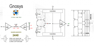
In audio art design this number is 24/40
The following discussion is provided, recognizing that
not all measured performance behavior explains or
correlates with listening tests by audio experts. The
design of the Gold gain ratio amp included consideration of both
objective performance measurements, as well as an
awareness of widely held theory on the success and
failure of previous amp designs.
the concept is important to break through the wall of the Natural Gain
(open loop gain)
SOUND QUALITY
The sound quality of an golden amp is often the crucial
selection criteria—even when a data sheet claims
exceptional distortion performance.
By its nature, sound quality is subjective.
Furthermore, results of listening
tests can vary depending on application and circuit
configuration. Even experienced listeners in controlled
tests often reach different conclusions.
Many audio experts believe that the sound quality of a
high performance FET buffer is superior to that of
bipolar op amps. A possible reason for this is that
bipolar designs generate greater odd-order harmonics
than FETs. To the human ear, odd-order harmonics
have long been identified as sounding more unpleasant
than even-order harmonics. FETs, like vacuum
tubes, have a square-law I-V transfer function which is
more linear than the exponential transfer function of a
bipolar transistor. As a direct result of this square-law
characteristic, FETs produce predominantly even-order
harmonics.
The golden ratio is also called the golden section (Latin: sectio aurea) or golden mean.Other names include extreme and mean ratio,medial section, divine proportion, divine section (Latin: sectio divina), golden proportion, golden cut, and golden number.
In audio art design this number is 24/40
The following discussion is provided, recognizing that
not all measured performance behavior explains or
correlates with listening tests by audio experts. The
design of the Gold gain ratio amp included consideration of both
objective performance measurements, as well as an
awareness of widely held theory on the success and
failure of previous amp designs.
the concept is important to break through the wall of the Natural Gain
(open loop gain)
SOUND QUALITY
The sound quality of an golden amp is often the crucial
selection criteria—even when a data sheet claims
exceptional distortion performance.
By its nature, sound quality is subjective.
Furthermore, results of listening
tests can vary depending on application and circuit
configuration. Even experienced listeners in controlled
tests often reach different conclusions.
Many audio experts believe that the sound quality of a
high performance FET buffer is superior to that of
bipolar op amps. A possible reason for this is that
bipolar designs generate greater odd-order harmonics
than FETs. To the human ear, odd-order harmonics
have long been identified as sounding more unpleasant
than even-order harmonics. FETs, like vacuum
tubes, have a square-law I-V transfer function which is
more linear than the exponential transfer function of a
bipolar transistor. As a direct result of this square-law
characteristic, FETs produce predominantly even-order
harmonics.
Attachments
Fully agree and add: it's even worse than that: the Golden Ratio applies to ***linear*** dimensions; Stee is comparing ***Logarithmic*** ones which does not make sense.Good to see Stee maintaining his usual standards!
The golden ratio is (1+sqrt(5))/2 ~= 1.618. 40/24 is 1.667 so does not even come close. Starting from a false premise is rarely a good way to approach engineering design.
Example: as a side Hobby I'm a Photographer, and must be aware of Composition Rules .
Often use the "Rule of Thirds" to quickly find the "points of interest" in a picture.
Now, I must (mentally) divide the space in ***linear*** thirds.
Using a Log scale would be ridiculous and produces whacky composed Pictures.
Which is what Elvee suggests.
By the way ..... what is "natural gain?"
Curious concept with no match in reality
Nope, he's going far beyond - take a look at the OPA604 ds, page 12...Good to see Stee maintaining his usual standards!

L.
No, you are wrong.
Natural Gain is not open loop gain but a certain gain setting which produces "Natural" or "Perfect" amplification, where the amplified end product bears a harmonious relation to the original one.
Open Loop gain is anything *but* that.
Clearly you are not even aware of the concept.
By the way, you *still* don't answer about your mistaken comparison of non linear (Log) dimensions instead of the proper linear ones.
Um... its just silly to say that the Golden Ratio is somehow the most glorious amplification level. Directly, its just as pointless as saying that the proper number of eggs to put in a package is 12. (In fact, isn't the Grand Metrification having Europe as its Leader, down-converting eggs to 10-to-the-box? What about wine? seems 12 is a case, the world around. No "five-packs" of beer yet, nor 10-packs for that matter. Hmmm....)
Let me take this someplace where Stee hasn't.
Optics.
We've all seen the lenses that are used in cameras. Maybe some of us remember back to the nicer cameras of the 1950s ... relatively tiny lenses, maybe one-surface multicoated, no zoom, no autofocus. But they worked. By the year 2010, lenses (on DSLRs) are much bigger hunks of plastic, way more elements, Zoom, autofocus, everything. Very cool, that somehow they don't cost more in constant dollars than the 1950s lenses.
Then there are these lenses that we never get to see, but upon which all electronics now depends: the chip-making photolithography lenses. They cost upward of $1,000,000 (some even as high as $3,000,000!). They have dozens of elements (individual lenses cemented together). Why so many?
EXACTLY ANALOGOUS to "amplification", lenses bend light through a series of angles, through materials that are imperfect in well known ways at dispersing the light itself. The tighter the bends, the fewer the number of lens-groups, but the poorer is the ultimate focus of the image plane. The big multimillion dollar chipmaking lenses use dozens of groups, so as to bend the light as little as possible within the design-framework. thus, they're able to almost entirely cancel out the various aberrations that would otherwise ruin their utility in making sub-optical wavelength images.
Connecting these dots, I have myself harbored the notion that if we just "throw out the 'economic principle'" of trying to deliver the "best" for the "most reasonable price" (whatever-the-hell that means), then an optimal amplifier would, like the multimillion dollar lenses, amplifier the signal the smallest reasonable amount per stage - with additive stage noise binding the lower limit. Indeed in the old tube-based oscilloscopes (with their "armies" of carefully matched dual-triode tubes), each stage was required to do very little amplification. This in turn preserved both bandwidth and absolute signal integrity.
Because... let's be clear: the amplification required from line-level signals to output is on the order of 30x to 300x - whether for Class D, B, AB, A, tube, transistor or anything between. That 1 volt of input becomes 30 volts (P2P) becomes about 15 watts at the low end; at 300 volts, its 1,500 watts. Amplifiers, though rarely "remembered" to have been designed such, amplify voltage up front near the input, then current in later stages, to give power.
I built an amplifier using all FETs (because I like 'em, being so similar to lower-voltage, heater less triode tubes), with voltage-amplification-per-stage of less than 2x ... yet it only takes 10 steps (2, 1.9, 1.8, 1.7... 1.2, 1.1) to give a voltage gain of 67; the final stage uses (like virtually all semiconductor setups) a complimentary emitter-follower configuration for current-gain, with matched FET-NPN Darlingtons, and very modest NFB. It was run class A throughout, though technically it has a push-pull final.
The result? Sweet ... at low volume, high, between. No apparent coloration, no odd speaker break-up or other nonlinear physics back-EMF issues. Trivial design (really), just using the same "million buck optics theory" approach. 75 watts out.
Stee's idea, using just the Golden Ratio is pretty bogus on its own. However, using many, small-gain, noise-controlled, complimentary stages ... is yet another theory that deserves its own merit.
GoatGuy
once the, 'you can't do that' people calm down,
something interesting might appear in this thread .
``````````````````````````````````````````````````````````
have a friend, who still takes his Speed Graphic with him everywhere ...
something interesting might appear in this thread .
``````````````````````````````````````````````````````````
Optics.
Maybe some of us remember back to the nicer cameras of the 1950s ...
have a friend, who still takes his Speed Graphic with him everywhere ...
Ok, let's be specific: Why do you consider the ratio between open and closed loop gain significant?.....the theme is set to gain ratio : Joker:.....
Do you believe the ratio is constant in an amplifier over the audio bandwidth so this can be a
meaningful design goal or are you assuming that setting it a particular frequency is adequate?
There is nothing so far to support your assertion.
http://www.esafono.it/1TO100RULE.pdf
is an aesthetic relationship of the acoustic scene
acts as a rebuilder of space as expander
is an aesthetic relationship of the acoustic scene
acts as a rebuilder of space as expander
Nothing new here, surely?
The document just described a low NFB amp with output transformer to lower output impedance.
I suspect it measures badly but sounds, what's that word I see around here, errr.. euphonic!
There is no Golden Rule for open loop to closed loop or loop gain ratio. These ratios will vary from design to design and from topology to topology and with performance goals; and as already stated, within a given design these parameters are not one dimensional, they vary with frequency, temperature and possibly more.
OK, no technical reason - just Stee's aesthetic number rules.http://www.esafono.it/1TO100RULE.pdf
is an aesthetic relationship of the acoustic scene
acts as a rebuilder of space as expander
These thematic designs you post and illustrate on your website are certainly imaginative and must make wonderful copy
for impressionable people to read but if the ideas crumble at the first level of inquiry, surely you must have doubts about
their value compared to established audio design theory. I don't mean to say categorically that you are wrong, if that
actually matters to you, but the onus is heavily on you to prove your claims by demonstrating that they can at least work
correctly as power amplifiers.
Otherwise, demonstrate their benefit by simulation or other evidence first. There are nebulous combinations of components
that can amplify audio but few ideas are worth building or even serious consideration. Let's see some that really can work
and deliver on the promise of the glowing descriptions and titles you give them.
I'm actually for a little imaginative thinking, perhaps as tomtt suggests, because this enables us to move on to new areas
and possibilities but you can't get there without a proven basis to build ideas on. That won't come out of the ether or from the
elaborations and chip-level techniques of opamps without a grounding in what is actually needed. Meantime, start simpler
and build from there - with purpose.
Last edited:
FWIW I found Stee's posts and links at an Australian Audio site.
*We* are showing lots of open mindness; there they weren't commented, not even to rebuke them.
The deafening silence of the open desert.
Looks like the Aussies are more practical minded than us, and don't have much time for idle pointless "discussions" ... or so it seems.
*We* are showing lots of open mindness; there they weren't commented, not even to rebuke them.
The deafening silence of the open desert.
Looks like the Aussies are more practical minded than us, and don't have much time for idle pointless "discussions" ... or so it seems.
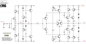
JMFahey ... for a certain amount of comedy, check out the design of post #11 ... after scratching my head endlessly, I think the entire "front end" is a do-nothing amplifier. Basically a fancy source-follower. The driven transistors on the righthand section certainly don't look power hungry. So... that and missing resistor values everywhere ... leads me to believe this is just "design salad".
Further apart from the enthusiastic 24/40 label of golden ratios, there appears to be nothing in the circuit that could achieve such precision.
GoatGuy
Further apart from the enthusiastic 24/40 label of golden ratios, there appears to be nothing in the circuit that could achieve such precision.
GoatGuy
- Status
- This old topic is closed. If you want to reopen this topic, contact a moderator using the "Report Post" button.
- Home
- Amplifiers
- Solid State
- the Golden Gain Ratio