Sure, the EMU seems to use 2Vrms as full scale? One other problem I have to work around is getting the full duplex to work at 24bits.
That's about right for a stock EMU0204 but you still shouldn't be able to display a noise floor that low. A stock EMU0204 with the gain control set to 0dB on the right unbalanced channel the majority of the signal is on one of the differential inputs to the ADC. The signal on the other dif input is tiny by comparison. The ADC is operated in a unbalance dif state. The one hot level input will saturate before the other. There is no way you can get the full balanced DR out of the ADC. That was the premiss for the simple mod I did on the unbalanced right channel. I haven't looked at the balanced left channel yet but I believe it's about the same when used unbalanced. If you short the input to either channel of the 0204 and increase the gain control the noise floor rises proportionally with the increase of gain.
I think you have a SW scaling problem.
I have other software FFT and can verify this.
Last edited:
It's before the filter.
Drat, you have done it the right way, so far there is nothing to complain about!
")
ES
I think you have a SW scaling problem.
I have other software FFT and can verify this.
We have different views on this, if I use an external preamp with a much lower noise floor I will change the reference level so I can display as much dynamic range as possible.
That's the whole idea behind notching out the fundamental, you don't/can't display its peak since it would saturate the A/D. -160db on my plot is ~17nV/rt-Hz not really that great. -150db on a 1V signal is 30nV/rt-Hz or so not great at all. The FFT does not matter the reference level is arbitrary and I would not use any software that did not have provisions for a preamp gain in front of the A/D.
I don't quite understand your point, once you use the variable gain on the inputs you have to calibrate your measurment. I took the output of the notch and turned up the gain to get a nice display, then I took a -60dB signal and put it into the same input changing nothing just using the reading to normalize. If you put a 1mV signal into the EMU0204 and turn the gain up to 60db you get a 0dB answer, so normalizing means subtract 60dB from everything. If I use a 1nV/rt-Hz pre-amp to amplify a small signal the display (noise floor) should end up at -180dB (for a 1Hz BW). Demian I corrected for the FFT BW, at 8K points it's around 6Hz or so.
Last edited:
That is a pitfall of using a variable wire wound pot for attenuating.
I should put together a fixed resistor attenuator.
Exactly how much THD are we talking about for a wire wound pot? I can't find any references on THD and potentiometers, either here or on Google. Wire wound pots have very low noise, and their bandwidth would be limited by any inductance and stray capacitance, but I don't know about THD.
I think it's fairly obvious that stray capacitance in a pot (or switched attenuator or digital attenuator) will affect bandwidth, but the amount of THD is not obvious to me. It should be comparable to any resistive divider, but I have nothing on it.
Dick
1/( 10 exp(db/20 - 2))
Or .0000562341%
ES
PS I used -125
As soon as everyone is satisfied with the SW and cal and emu dynamic range et al, we'll get a better feel for what the level is compared to others.
If it is still .00006-ish then that is useful for many DIY'ers. However, if the thd can belowered more, then it will be compititive with the other commercial ultra-low distortion oscillators out there. With opamp changes and some tuning/trimming of R's, my K-H 4402B for example does .000045% thd. Other s are as low or lower. Can the 2H be lowered?
Thx-RNMarsh
Exactly how much THD are we talking about for a wire wound pot?
That very much depends on how you use it. If you use it as pure divider (one end driven from a low-Z source; other end grounded; no current flowing through the divider (i.e. facing a high-Z input)), its distortion contribution will be very small. I can't measure any distortion from an ordinary 10k cermet multi-turn trimmer in such an operating mode (harmonics near/below the measurement floor of about -130 dB, with 1 kHz/+16 dBu at the input of the trimmer), and with a wirewound part it would be even lower.
If you draw significant current through the wiper, the very nonlinear contact resistance will come into play. The magnitude is very variable, from type to type and from specimen to specimen. Also expect it to be a function of wiper position and probably also dependent on usage/wear. I have given some figures for cermet trimmers in this thread; probably a wirewound pot will be better, but expect no magic unless proven.
Certainly a fixed attenuator is the much more dependable means. Preferably you build it out of series connected equal value resistors, and make sure to keep the voltage across each to about 2 Vrms or less, and the power dissipation to 2 mW or less (that's for ordinary 1/4 W, 50 ppm metal film parts, and a distortion goal of < -140 dB).
Samuel
As soon as everyone is satisfied with the SW and cal and emu dynamic range et al, we'll get a better feel for what the level is compared to others.
If it is still .00006-ish then that is useful for many DIY'ers. However, if the thd can belowered more, then it will be compititive with the other commercial ultra-low distortion oscillators out there. With opamp changes and some tuning/trimming of R's, my K-H 4402B for example does .000045% thd. Other s are as low or lower. Can the 2H be lowered?
Thx-RNMarsh
I don't know which parts Scott is using. If he is using carbon film resistors and mylar capacitors the answer is it can go a lot lower. If he is using dale brownies and polyprop capacitors and a decent op amp then the answer is possibly still a bit.
As I thought he was using an AD797 which is specified for -120 db (20Khz) at 3 Volts out, he seems to be very near that limit. He can get a bit more by following with a passive filter, or going to a balanced design.
But what he has shown is that anyone with a sound card and $20.00 worth of parts can go state of the art.
ES
We have different views on this, if I use an external preamp with a much lower noise floor I will change the reference level so I can display as much dynamic range as possible.
That's the whole idea behind notching out the fundamental, you don't/can't display its peak since it would saturate the A/D. -160db on my plot is ~17nV/rt-Hz not really that great. -150db on a 1V signal is 30nV/rt-Hz or so not great at all. The FFT does not matter the reference level is arbitrary and I would not use any software that did not have provisions for a preamp gain in front of the A/D.
I don't quite understand your point, once you use the variable gain on the inputs you have to calibrate your measurment. I took the output of the notch and turned up the gain to get a nice display, then I took a -60dB signal and put it into the same input changing nothing just using the reading to normalize. If you put a 1mV signal into the EMU0204 and turn the gain up to 60db you get a 0dB answer, so normalizing means subtract 60dB from everything. If I use a 1nV/rt-Hz pre-amp to amplify a small signal the display (noise floor) should end up at -180dB (for a 1Hz BW). Demian I corrected for the FFT BW, at 8K points it's around 6Hz or so.
Okay so it's gain scaled. Just wanted to know how you got that. And yes this is a big advantage of using the notch.
Exactly how much THD are we talking about for a wire wound pot? I can't find any references on THD and potentiometers, either here or on Google. Wire wound pots have very low noise, and their bandwidth would be limited by any inductance and stray capacitance, but I don't know about THD.
I think it's fairly obvious that stray capacitance in a pot (or switched attenuator or digital attenuator) will affect bandwidth, but the amount of THD is not obvious to me. It should be comparable to any resistive divider, but I have nothing on it.
If the wiper is a different metal type from the wind micro layer corrosion on the surfaces form a diode. That's one source of the distortion.
Working the pot will remove or displace the corrosion. If the pot is in a sealed case adding a bag of silicate descant is helpful.
Last edited:
That very much depends on how you use it. If you use it as pure divider (one end driven from a low-Z source; other end grounded; no current flowing through the divider (i.e. facing a high-Z input)), its distortion contribution will be very small. I can't measure any distortion from an ordinary 10k cermet multi-turn trimmer in such an operating mode (harmonics near/below the measurement floor of about -130 dB, with 1 kHz/+16 dBu at the input of the trimmer), and with a wirewound part it would be even lower.
If you draw significant current through the wiper, the very nonlinear contact resistance will come into play. The magnitude is very variable, from type to type and from specimen to specimen. Also expect it to be a function of wiper position and probably also dependent on usage/wear. I have given some figures for cermet trimmers in this thread; probably a wirewound pot will be better, but expect no magic unless proven.
Certainly a fixed attenuator is the much more dependable means. Preferably you build it out of series connected equal value resistors, and make sure to keep the voltage across each to about 2 Vrms or less, and the power dissipation to 2 mW or less (that's for ordinary 1/4 W, 50 ppm metal film parts, and a distortion goal of < -140 dB).
Samuel
Hi Samuel,
Can you put a number to "significant current"?
But what he has shown is that anyone with a sound card and $20.00 worth of parts can go state of the art.
ES
A sound card and a high Q BP filter ... would be same concept as my suggestion #2360, earlier.... a different source but still thru a high Q BP filter.
Just waiting for Scott to finish his work and show the schematic to be presented.
I am still looking for SOTA thd levels and thd+n levels..... we get close... I have been close.... but not there yet.
Thx-RNMarsh
Last edited:
Dick,
I know Scott is confused but you may be also.
A Wein bridge is a combination of two resistors and two capacitors that when fed across the bridge have a strong resonance at the output.
This may be combined with an amplifier to form an oscillator. To get minimum distortion the gain of the amplifier has to exactly match the loss in the Wein bridge. The usual method to do that is to monitor the output voltage and make gain changes based on the level. If the level is rising without control the amplifier will clip. If the gain is too low the oscillations will stop.
Now when the gain is too low the circuit will resonate. Think of a tuning fork, it is a resonator as are crystals and bells. When you strike a bell it rings at it's resonant frequency and with decreasing amplitude. Now if you strike the bell every few seconds it will ring but the level goes up at each strike and drops until the next strike.
What we do with a Wein Resonator is strike it at the resonant frequency. This is different than a filter. (Subtle but important).
Now you can follow the resonator with a filter to clean up the distortion from using real world parts. This can be done simply with a Wein bridge driven from the output. To reduce loading effects the grounded R may be tapped to give a lower level and lower impedance source.
Now if you use state of the art parts such as bulk metal resistors and rel caps (I think you have heard if them. ) you can get very low distortion of say -130 db.
You also asked about predistortion this is easily done by using two identical op amps in series with each one having half the gain of the system. The second harmonic generated by the first amp will be canceled by the second harmonic in the second stage.
Now to get to -140 db or better you will also have to consider issues such as the PC material. Glass epoxy due to the woven glass has impedence bumps even along the traces. So a more uniform modern dielectric based PC material should be used. A silver played copper enclosure is possibly even useful at these levels.
Now another issue raised by Nelson P is the open loop gain of the op amps. As the perfect op amp has a smooth HF roll off of 6 db per octave that results from optimum damping. As there is some stray inductance and capacitance there may be a bump or slouch at the start if the roll off. By increasing the gain and reducing the signal we can to a certain extent tweak damping.
Of course another issue is what power supply drives the circuit. Now that is a rather complicated issue and more than I want to get into at the moment.
ES
Posted from my cellphone and its just too hard to fix the typos.
I know Scott is confused but you may be also.
A Wein bridge is a combination of two resistors and two capacitors that when fed across the bridge have a strong resonance at the output.
This may be combined with an amplifier to form an oscillator. To get minimum distortion the gain of the amplifier has to exactly match the loss in the Wein bridge. The usual method to do that is to monitor the output voltage and make gain changes based on the level. If the level is rising without control the amplifier will clip. If the gain is too low the oscillations will stop.
Now when the gain is too low the circuit will resonate. Think of a tuning fork, it is a resonator as are crystals and bells. When you strike a bell it rings at it's resonant frequency and with decreasing amplitude. Now if you strike the bell every few seconds it will ring but the level goes up at each strike and drops until the next strike.
What we do with a Wein Resonator is strike it at the resonant frequency. This is different than a filter. (Subtle but important).
Now you can follow the resonator with a filter to clean up the distortion from using real world parts. This can be done simply with a Wein bridge driven from the output. To reduce loading effects the grounded R may be tapped to give a lower level and lower impedance source.
Now if you use state of the art parts such as bulk metal resistors and rel caps (I think you have heard if them.
) you can get very low distortion of say -130 db. You also asked about predistortion this is easily done by using two identical op amps in series with each one having half the gain of the system. The second harmonic generated by the first amp will be canceled by the second harmonic in the second stage.
Now to get to -140 db or better you will also have to consider issues such as the PC material. Glass epoxy due to the woven glass has impedence bumps even along the traces. So a more uniform modern dielectric based PC material should be used. A silver played copper enclosure is possibly even useful at these levels.
Now another issue raised by Nelson P is the open loop gain of the op amps. As the perfect op amp has a smooth HF roll off of 6 db per octave that results from optimum damping. As there is some stray inductance and capacitance there may be a bump or slouch at the start if the roll off. By increasing the gain and reducing the signal we can to a certain extent tweak damping.
Of course another issue is what power supply drives the circuit. Now that is a rather complicated issue and more than I want to get into at the moment.
ES
Posted from my cellphone and its just too hard to fix the typos.
Last edited:
Dick,
I know Scott is confused but you may be also.
A Wein bridge is a combination of two resistors and two capacitors that when fed across the bridge have a strong resonance at the output.
This may be combined with an amplifier to form an oscillator. To get minimum distortion the gain of the amplifier has to exactly match the loss in the Wein bridge. The usual method to do that is to monitor the output voltage and make gain changes based on the level. If the level is rising without control the amplifier will clip. If the gain is too low the oscillations will stop.
Now when the gain is too low the circuit will resonate. Think of a tuning fork, it is a resonator as are crystals and bells. When you strike a bell it rings at it's resonant frequency and with decreasing amplitude. Now if you strike the bell every few seconds it will ring but the level goes up at each strike and drops until the next strike.
What we do with a Wein Resonator is strike it at the resonant frequency. This is different than a filter. (Subtle but important).
Now you can follow the resonator with a filter to clean up the distortion from using real world parts. This can be done simply with a Wein bridge driven from the output. To reduce loading effects the grounded R may be tapped to give a lower level and lower impedance source.
Now if you use state of the art parts such as bulk metal resistors and rel caps (I think you have heard if them.
You also asked about predistortion this is easily done by using two identical op amps in series with each one having half the gain of the system. The second harmonic generated by the first amp will be canceled by the second harmonic in the second stage.
Now to get to -140 db or better you will also have to consider issues such as the PC material. Glass epoxy due to the woven glass has impedence bumps even along the traces. So a more uniform modern dielectric based PC material should be used. A silver played copper enclosure is possibly even useful at these levels.
Now another issue raised by Nelson P is the open loop gain of the op amps. As the perfect op amp has a smooth HF roll off of 6 db per octave that results from optimum damping. As there is some stray inductance and capacitance there may be a bump or slouch at the start if the roll off. By increasing the gain and reducing the signal we can to a certain extent tweak damping.
Of course another issue is what power supply drives the circuit. Now that is a rather complicated issue and more than I want to get into at the moment.
ES
Posted from my cellphone and its just too hard to fix the typos.
Ed,
Not to be picky, but a Wein Bridge is a very low-Q passive arrangement. To the best of my knowledge, there is no such thing as a Wein Resonator, unless you are referring to a Wein Bridge in an active, oscillator-like arrangement.
A conventional Wein Bridge has a broadly-based minimum loss of 1/3 at its center frequency. A typical Wein Bridge oscillator is built by taking an X3 non-inverting gain stage and connecting the Wein Bridge as a positive-feedback network around it. At the center frequency the non-inverting loop gain is unity and it oscillates.
The non-inverting gain of 3 amplifier is usually built from an op amp, so you end up having frequency-dependent positive feedback through the Wein Bridge and flat negative feedback through a resistive network to the inverting input of the op amp. The AGC is usually applied to control the amount of flat negative feedback. The passive Wein Bridge is a low-Q device that obtains a high-Q behavior by being embedded in a circuit with positive feedback.
A high-Q bandpass filter can be made from the Wein Bridge oscillator arrangement by having the amount of negative feedback be slightly stronger than the amount needed for osillation, and by feeding the signal input into the inverting input of the op amp.
Cheers,
Bob
Bob,
When you have what would be an oscillator without a level detector and gain adjust set just below oscillation you have a device that rings.
Scott refers to it as regeneration, but technically it is a resonator.
If you treat it as a black box and compare it to a tuning driven tuning fork, you would be hard pressed to see any difference.
ES
There are many ways to make a sinewave oscillator. I havent seen the SWNO schematic yet. Cant make any comments without a schematic. But the distortion numbers are pretty good... and that's all. (?) Seems like it can be simple and easy to make, too. Maybe?
Thx-RNMarsh
Thx-RNMarsh
Last edited:
Ok,
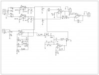
I can show you the resonator version at least.
Here is the way I did it for my AC power line article.
All you need is the Wein bridge section. You won't need the power line clipper or the output buffers. Just drive it with a very stable oscillator.
ES
I can show you the resonator version at least.
Here is the way I did it for my AC power line article.
All you need is the Wein bridge section. You won't need the power line clipper or the output buffers. Just drive it with a very stable oscillator.
ES
Attachments
As you all know.... I put down the gauntlet to challenge the best of the best around here to get to -140.... at first it was THD+N but as has been demonstrated that isnt likely possible. But lets get the Noise as low as is reasonable while the THD is -140 re 1V/1KHz into >600 Ohms (even into 1-10K is fine). And can it be done at 10KHz? The issues of build quality, parts, shielding, grounding, PCB material and all the rest are all do-able if the circuit is capable of doing it in the first place.
-120 to -130dB's (THD) is currently the 'ultra' level of performance... for quit some time now. With today's best available opamps and practices, another 10-20db is currently and possibly far into the future, the highest attainable SOTA. How close can we come to it in practice?
And, are there any currently published circuits that can do it - and have been tested/proven by people here/3rd parties.... because some seem to be questionable as to their practicality in operation if they can do what is claimed.
Thx-RNMarsh
Last edited:
Ok,
I can show you the resonator version at least.
Here is the way I did it for my AC power line article.
All you need is the Wein bridge section. You won't need the power line clipper or the output buffers. Just drive it with a very stable oscillator.
ES
Looks like a high Q BP filter to me.
-RNM
Bob,
When you have what would be an oscillator without a level detector and gain adjust set just below oscillation you have a device that rings.
Scott refers to it as regeneration, but technically it is a resonator.
If you treat it as a black box and compare it to a tuning driven tuning fork, you would be hard pressed to see any difference.
ES
Of course. No disagreement there. I just thought your explanation was potentially misleading. As I pointed out, a Wein Bridge in and of itself is not a resonator and is fundamentally of low Q. Add some amplification and you get something that has significant Q and can be called a resonator, if you like.
BTW, I'm not sure it is fully correct to call any circuit, active or passive, that rings, a resonator. Obviously passive things like L-C circuits, crystals and tuning forks are resonators. It is less clear to me that an R-C circuit that is actively made to ring is a resonator. Is a poorly designed negative feedback power amplifier that rings a resonator? I'm not disagreeing with you, just scratching my head over semantics. Maybe I should look up resonator on Wikipedia or something.
Cheers,
Bob
- Home
- Design & Build
- Equipment & Tools
- Low-distortion Audio-range Oscillator