Well, if we use a VFA in a inverting configuration, we are in this best situation. But, if we use the non inverting configuration, the feedback signal will have to across the - input stage BEFORE to be subtracted. This active stage will ADD its own distortion and delay to the feedback signals.
We add errors to the errors we want to cancel, we do not cancel them.
Let push this to absurd: this - input stage cancel exactly the distortion of the amplifier, including the ones generated in the + input stage ? You had suppressed the amplifier distortion from the feedback signal: the feedback will not cancel any distortion, just reduce the gain.
Am-i clear ?
No. What you are describing (larger distortions in non-inverting VFAs) is nothing more than "common mode distortions" - no need for any more convoluted interpretations. In an non-inverting configuration, the opamp input will see the full input signal as a common mode swing, so any common mode nonlinearities are adding up. In inverting configurations, the opamp input is essentially to (a virtual) ground, so no common mode effects. This has essentially nothing to do with the VFA or the standard CFA topology.
No. What you are describing (larger distortions in non-inverting VFAs) is nothing more than "common mode distortions" - no need for any more convoluted interpretations. In an non-inverting configuration, the opamp input will see the full input signal as a common mode swing, so any common mode nonlinearities are adding up. In inverting configurations, the opamp input is essentially to (a virtual) ground, so no common mode effects. This has essentially nothing to do with the VFA or the standard CFA topology.
I tried to explain this to the CFA fans, but with no avail.
I want to say something about TMC.
Someone says TMC does add a pole in the system. I cannot deny that, but why we don't see the extra pole from the loop gain? Here is my observation.
You will only see that pole if you remove Miller capacitor. There is a phenomenon called "pole splitting". Extra TMC pole will only become problem when the OPS is driven by current source. However, with the "help" of Miller Capacitor, the VAS output impedance is quite low(normally less than 100 Ohm when frequency is high). OPS is more likely to be voltage driven at high frequency. In that case, the extra pole created by TMC is pushed to a relatively high frequency(e.g 10MHz). This phenomenon is called as "pole splitting".
Below I quote the description on Wiki Pole splitting - Wikipedia, the free encyclopedia
----------------------
When a capacitor is introduced between the input and output sides of the amplifier with the intention of moving the pole lowest in frequency (usually an input pole) to lower frequencies, pole splitting causes the pole next in frequency (usually an output pole) to move to a higher frequency. This pole movement increases the stability of the amplifier and improves its step response at the cost of decreased speed.
-----------------------
Also note the value of pole-zero compensation: http://www.diyaudio.com/forums/soli...ut-2-pole-compensation-vas-2.html#post2375354 ...
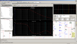
Here is my latest TPC simulation.
The goal is to achieve TPC without huge overshoot.
The TPC network around VAS actually create not only 2 poles, but also a ZERO.
The ZERO is the demon which causes overshoot. (After hours working on Maths, I found 2 poles is quite stable after you applying global feedback. The extra Zero is the one causes overshoot)
I use C7 and R23 to create another Pole to cancel the Zero.
Since 2 poles system is not stable after you close the loop, I must create another Zero at global feed back network. See C10. Because the Zero is not in foreword pass, it won't cause overshoot.
First pic is the loop gain and 100KHz square wave.
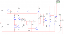
Second pic is the schematic.
The goal is to achieve TPC without huge overshoot.
The TPC network around VAS actually create not only 2 poles, but also a ZERO.
The ZERO is the demon which causes overshoot. (After hours working on Maths, I found 2 poles is quite stable after you applying global feedback. The extra Zero is the one causes overshoot)
I use C7 and R23 to create another Pole to cancel the Zero.
Since 2 poles system is not stable after you close the loop, I must create another Zero at global feed back network. See C10. Because the Zero is not in foreword pass, it won't cause overshoot.
First pic is the loop gain and 100KHz square wave.
Second pic is the schematic.
Attachments
kgrlee said:I'll point out that the 'distortion cancelling capacitor' (Cn in figs 28 & 29 and C2 in fig 41) is actually a 'pure Cherry'.
I'm suitably reprimanded. I was confusing Guru Wurcers iconic design with one of my own crude efforts.Since the forward path is the same with or without it (except for small second order effects at high frequencies), I don't see the arguement for this. It affects neither the crossover nor phase response at crossover in more than a trivial way.

Yes.
Each and every amp that is Miller compensated (which makes prolly about 99% of the current market). Conditional stability is strictly related to compensation methods of the 2nd (or larger) order.
.
Most are only conditionaly stable , miller compensation or not ,
you ll hardly find one that can be set at 0db CLG.
The old but still excellent Accuphase P300 dual differential VFA
power amp section has one of the lowest CLG i ve ever seen , at 18db or so , and it is shunt compensated....
I'm suitably reprimanded. I was confusing Guru Wurcers iconic design with one of my own crude efforts.
No problem let's all try and learn something we didn't know yesterday, that way we all win.
Yes he can. Similarly we can forget to buy the book. I made that decision round about the time Doug admitted that an entire chapter was so bad it needs to be completely rewritten, but he doesn't have the time now so it will remain unchanged in the new edition.
I've noticed that his responses to suggestions tend to fall broadly into one of three categories:
- You'll be glad to know that's already in the next edition.
- That would be a valuable addition. Unfortunately it's now too late to include it in the next edition.
- I don't want to cover that subject in my book.
That makes me wonder about the accuracy of the thread title and the first post. Does he really want our opinions, or does he just want to generate interest in the new edition, in the hope that we'll buy it?
Perhaps this thread should be moved to the commercial sector.
p.s. Come to think of it, I remember feeling much the same way about his previous thread advertising the (then) upcoming book on crossovers.

I think you've nailed it!
there are at least 2 that are popular for defining "unconditional stability"
Bode/Nyquist stability as gain devices warm up, their gain sweeping form 0 to normal operating value - important with tubes - not so justifiable with SS
http://www.diyaudio.com/forums/soli...terview-negative-feedback-66.html#post1162866
and stability to "any" load - usually arbitrary passive load with big, high Q C being a problem for many audio amps
some make a fetish of arbitrary C load stability without series L - I don't see the point - use a uH inductor and you're done
Most are only conditionaly stable , miller compensation or not ,
you ll hardly find one that can be set at 0db CLG...
Waly uses it in the first sense the JCX lists while Wahab and Damir (Dadod) use "unconditional stability" in a third way. Stable with any amount of feedback. This probably explains the dispute with Waly since that is not the common use of the term (in English at least).
Best wishes
David
Last edited:
Unfortunately, I don't think it's possible to design a TMC+TPC amp that is unconditionally stable (pretty easy to understand why)
Don't see why not. The Hilbert transform means it takes a while for the phase to accumulate.
Bode's Maximum Feedback is not even a rational function and has arbitrarily steep Bode plot - but not for very far! So the system could be unconditionally stable with correct pole + zero placement. Whether it is worth the effort is a different question.
Best wishes
David
Waly uses it in the first sense the JCX lists while Wahab and Damir (Dadod) use "unconditional stability" in a third way. Stable with any amount of feedback. This probably explains the dispute with Waly since that is not the common use of the term (in English at least).
Best wishes
David
I am not sure that Waly did not uses "unconditional stability" in a third way. Stable with any amount of feedback.
BR Damir
Waly uses it in the first sense the JCX lists while Wahab and Damir (Dadod) use "unconditional stability" in a third way. Stable with any amount of feedback. This probably explains the dispute with Waly since that is not the common use of the term (in English at least).
If that is the case, why did Waly not clear it up at the outset? It was clear which definition Dadod was using. Waly, perhaps you should give your definition.
They are all only conditionally stable, meaning there are closed loop gains at which these amps are not stable (that is, where the phase hits 180 degrees before the ULGF). While this is unlikely to happen during normal operation (although I would carefully check the stability when the output approaches the rails), during power up and power down such amps do have the nasty habit to burst into oscillations.
I am not sure that Waly did not uses "unconditional stability" in a third way. Stable with any amount of feedback.
BR Damir
The post shows clearly that he means it in the first sense.
If that is the case, why did Waly not clear it up at the outset? It was clear which definition Dadod was using. Waly, perhaps you should give your definition.
He did so, see above, before Dadod and Wahab.
Debate this with Waly if you want, I just wanted to avoid a useless debate with the observation that Damir and Wahab did not use the term in the usual way that a native speaker probably would.
Best wishes
David
OK. now Bonsai uses it like Dadod!
Self always uses it in the first sense and that seems to be more common, at least in the audio community.
It would make sense the op-amp community may have a different convention, their issues are different.
Last edited:
The post shows clearly that he means it in the first sense.
He did so, see above, before Dadod and Wahab.
Debate this with Waly if you want, I just wanted to avoid a useless debate with the observation that Damir and Wahab did not use the term in the usual way that a native speaker probably would.
Best wishes
David
Hi David,
This is my last about unconditionally stable amp and I think that native or no native speakers it’s technical definition.
I found this:
but what Waly wrote it is not close to this definition:Unconditionally stable refers to an amplifier that will not oscillate regardless of load or
source impedance.
and thenThey are all only conditionally stable, meaning there are closed loop gains at which these amps are not stable (that is, where the phase hits 180 degrees before the ULGF). While this is unlikely to happen during normal operation (although I would carefully check the stability when the output approaches the rails), during power up and power down such amps do have the nasty habit to burst into oscillations
Hi means that only an amp with first order of the compensation(6dB/octave slope) could be unconditionally stable.Each and every amp that is Miller compensated (which makes prolly about 99% of the current market). Conditional stability is strictly related to compensation methods of the 2nd (or larger) order.
and that is clearly connected with stability at all close loop gains, one included, nothing about the load or source impedance.
BR Damir
Most are only conditionaly stable , miller compensation or not ,
you ll hardly find one that can be set at 0db CLG.
The old but still excellent Accuphase P300 dual differential VFA
power amp section has one of the lowest CLG i ve ever seen , at 18db or so , and it is shunt compensated....
Not sure if we are talking about the same "conditional stability", but I would otherwise appreciate if you could educate me on how can a dominant pole, Miller compensated, amplifier be "conditionally stable" if the phase is strictly linear.
Hi Douglas.
Your circuits made great use of the MJ802/4502 pairs.
I actually built an amp with these devices in the early 70's and a great performer it was too. I still have it and it still works well.
In your plots for 'sustained beta', these are not included for comparison with the other devices, so can you say how do they compare? I always felt at the time these were streets ahead of anything alse available at the time.
I do remember they were very expensive at around 10 times the cost of a 3055, but fortunately I had a generous employer who donated a couple of pairs.
On another note, I recently acquired what appeared to be a very mundane amp, a Toshiba SBM20, but amazingly the circuit seems to follow your blameless design with CFP pairs on the outputs. It performs incredibly well, aspecially considering you'd be lucky to get a tenner if trying to sell it at a boot sale or audiojumble. Dit you play a part in it's conception?
Regards
Henry
Hi David,
This is my last about unconditionally stable amp and I think that native or no native speakers it’s technical definition.
I found this:
but what Waly wrote it is not close to this definition:
and then
Hi means that only an amp with first order of the compensation(6dB/octave slope) could be unconditionally stable.
and that is clearly connected with stability at all close loop gains, one included, nothing about the load or source impedance.
BR Damir
Now I see, there's a debate about the definition of "conditional stability". Here's mine:
Texas Instruments said:The gain-frequency characteristic of the amplifier and its feedback network must be such that oscillation does not occur. To meet this condition, the phase shift through amplifier and feedback network must never exceed 180° for any frequency where the gain of the amplifier and its feedback network is greater than unity. In practical applications, the phase shift should not approach 180° since this is the situation of conditional stability. Obviously the most critical case occurs when the attenuation of the feedback network is zero.
Hi means that only an amp with first order of the compensation(6dB/octave slope) could be unconditionally stable.
No - amplifiers with a dominant pole are always unconditionally stable. But higher order compensated amplifiers can also be unconditionally stable, if properly designed. See the above reference from TI.
Last edited:
- Status
- This old topic is closed. If you want to reopen this topic, contact a moderator using the "Report Post" button.
- Home
- Amplifiers
- Solid State
- Audio Power Amplifier Design book- Douglas Self wants your opinions