Hi guys,
I finally did some testing today. Both amps work well, and the sound is clean and nice, for a little while.
After a few minutes of operation of light listening (or instantly - if you raise the volume enough) the amps start acting weird. I guess they start oscillating, but I'm not really sure (never experienced that before, and this is my first proper DIY amp). There's some strange high pitched noise in the speakers, and the scope goes totally nuts (the screen basically gets covered by lines, and adjusting it doesn't help). Turning the amps off for a minute or two solves the problem, but it comes back just as easily.
Now, here's what I think is the issue: when this happens, the power draw jumps up to 70mA per rail, as opposed to the normal 40mA. And the driver transistors (BD140) get really hot. You can see the two tiny heatsinks on my pictures. Those are actually only temporary solutions, I was planning on mounting the drivers to the main heatsink (but I didn't have any insulators for them). I hope that will solve this problem.
About the standoffs - they came with the heatsink, and I think they're of some sort of heat-resistant material.
Have a nice day, all.")
I finally did some testing today. Both amps work well, and the sound is clean and nice, for a little while.
After a few minutes of operation of light listening (or instantly - if you raise the volume enough) the amps start acting weird. I guess they start oscillating, but I'm not really sure (never experienced that before, and this is my first proper DIY amp). There's some strange high pitched noise in the speakers, and the scope goes totally nuts (the screen basically gets covered by lines, and adjusting it doesn't help). Turning the amps off for a minute or two solves the problem, but it comes back just as easily.
Now, here's what I think is the issue: when this happens, the power draw jumps up to 70mA per rail, as opposed to the normal 40mA. And the driver transistors (BD140) get really hot. You can see the two tiny heatsinks on my pictures. Those are actually only temporary solutions, I was planning on mounting the drivers to the main heatsink (but I didn't have any insulators for them). I hope that will solve this problem.
About the standoffs - they came with the heatsink, and I think they're of some sort of heat-resistant material.
Have a nice day, all.
Last edited:
That is not normal at all: these amplifiers should draw something like 150~200mA, the exact value is not critical, but 40mA is completely wrong: there must still be an error somewhere, meaning one of the loops is operating on the edge, or even completely outside.Now, here's what I think is the issue: when this happens, the power draw jumps up to 70mA per rail, as opposed to the normal 40mA.
Double check again the transistors pin-out, resistor values, etc.
If you are unable to find anything, post an exact schematic with all devices and values you have actually used, and some good pics of your board.
Ouput device data from Elvee:
Higher quality score = more suitable
2SD1047_____Quality Score:__1.76
MJ(L)21194__Quality_Score:__1.60
MJ(W)21196__Quality_Score:__1.45
MJ15022,4___Quality_Score:__1.20
BD249C______Quality_Score:__1.04
MJ15003_____Quality_Score:__0.94
MJ802_______Quality_Score:__0.71
MJ15015_____Quality_Score:__0.55
MJE3055_____Quality_Score:__0.46
TIP41_______Quality_Score:__0.43
2N3055______Quality_Score:__0.35
TIP33_______Quality_Score:__0.34
BD911_______Quality_Score:__0.29
TIP3055_____Quality_Score:__0.16
Lower quality score = less suitable
So, good devices from this table include: 2SD1047, MJ21194, MJL21194, MJW21194, NJ21194, NJL21194, NJW21194, MJ21196, MJL21196, MJW21196, NJ21196, NJL21196, NJW21196, MJ15022, NJ15022, MJ15024, NJ15024, BD249C, MJ15003, NJ15003, MJ802, NJ802. Can you find any of these?
That is not normal at all: these amplifiers should draw something like 150~200mA, the exact value is not critical, but 40mA is completely wrong: there must still be an error somewhere, meaning one of the loops is operating on the edge, or even completely outside.
Double check again the transistors pin-out, resistor values, etc.
If you are unable to find anything, post an exact schematic with all devices and values you have actually used, and some good pics of your board.
Sorry, those figures appear to be quite inaccurate. I was just going by the digital displays of the two individual bench power supplies (used together in order to get a +/- supply) I used for testing. Now, hooked up to its dedicated power supply, I get different readings (when used in line with an ampere meter). 260mA for the positive rail and - oddly - 410mA for the negative one. I did notice that the transformer does not seem to be perfectly even, I get +29V and -28.8V... 23 watt total power draw from the mains.
Also, my amps are configured for 30 volt supplies (13 + 16 volt zeners and 39K resistor), and clearly that's not what I have. Is that an issue?
PS: I listened to this all day yesterday. Sounds really fantastic. I normally do not hear a difference between amps, but this is an exception. I can listen much louder without the sound piercing my ears. Clearly a good sign.
i aleardy have 3 d1047 from the previous amp and im pretty sure i can find another one,if not i wil use tip41 or 2n3055Ouput device data from Elvee:
Higher quality score = more suitable
2SD1047_____Quality Score:__1.76
MJ(L)21194__Quality_Score:__1.60
MJ(W)21196__Quality_Score:__1.45
MJ15022,4___Quality_Score:__1.20
BD249C______Quality_Score:__1.04
MJ15003_____Quality_Score:__0.94
MJ802_______Quality_Score:__0.71
MJ15015_____Quality_Score:__0.55
MJE3055_____Quality_Score:__0.46
TIP41_______Quality_Score:__0.43
2N3055______Quality_Score:__0.35
TIP33_______Quality_Score:__0.34
BD911_______Quality_Score:__0.29
TIP3055_____Quality_Score:__0.16
Lower quality score = less suitable
So, good devices from this table include: 2SD1047, MJ21194, MJL21194, MJW21194, NJ21194, NJL21194, NJW21194, MJ21196, MJL21196, MJW21196, NJ21196, NJL21196, NJW21196, MJ15022, NJ15022, MJ15024, NJ15024, BD249C, MJ15003, NJ15003, MJ802, NJ802. Can you find any of these?
PS: I listened to this all day yesterday. Sounds really fantastic. I normally do not hear a difference between amps, but this is an exception. I can listen much louder without the sound piercing my ears. Clearly a good sign.
It happened to me too, when I built the Circlophone, I had the P3A and The Leach (both DIY) but what amazes me is that, this compact beauty sounds so good even on brandless crappy pair of speakers
I still wanted to build another one, it could also be Piersma's CFP or Terranigma's Darlington Circlophone PCB
Hello everyone!
I realize now the DX Super A DestroyerX but I found circlophone really interesting and I also realize it.
I have some 2N1711 I think to put Q5 and Q6.
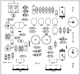
I designed a circuit that apparently has no errors but I do not know if it is well optimized, so if you have suggestions, do not hesitate to tell me.
Regards!
Hello everyone!
I realize now the DX Super A DestroyerX but I found circlophone really interesting and I also realize it.
I have some 2N1711 I think to put Q5 and Q6.
I designed a circuit that apparently has no errors but I do not know if it is well optimized, so if you have suggestions, do not hesitate to tell me.
Regards!
Attachments
Hello everyone!
I realize now the DX Super A DestroyerX but I found circlophone really interesting and I also realize it.
I have some 2N1711 I think to put Q5 and Q6.
I designed a circuit that apparently has no errors but I do not know if it is well optimized, so if you have suggestions, do not hesitate to tell me.
Regards!
Hello Project16!
I like your layout. I think Circlophone is going to be amp that have most altered PCB revisions. On first sight, placement of D4 looks weird. D4's cathode must go to Q8's collector directly.
2N1711 has only 50V Vce which limits rail voltage usage up to 25V. Cob is 18pF but there are many other good alternatives for Q5 and Q6.
EDIT: I see many other errors in layout. You have to check whole circuit from scratch imho.
Last edited:
260mA is highish, but acceptable. 410mA is problematic: it is too much, and worse, it is unequal. There is still something not quite right in your amp, and the 150mA difference current must end somewhere, probably in the speakerSorry, those figures appear to be quite inaccurate. I was just going by the digital displays of the two individual bench power supplies (used together in order to get a +/- supply) I used for testing. Now, hooked up to its dedicated power supply, I get different readings (when used in line with an ampere meter). 260mA for the positive rail and - oddly - 410mA for the negative one. I did notice that the transformer does not seem to be perfectly even, I get +29V and -28.8V... 23 watt total power draw from the mains.
Not at allAlso, my amps are configured for 30 volt supplies (13 + 16 volt zeners and 39K resistor), and clearly that's not what I have. Is that an issue?
Last edited:
Now, hooked up to its dedicated power supply, I get different readings (when used in line with an ampere meter). 260mA for the positive rail and - oddly - 410mA for the negative one. I did notice that the transformer does not seem to be perfectly even, I get +29V and -28.8V... 23 watt total power draw from the mains.
Excerpt from post 1:
*Checking R21, click here > Elvee said: "Measure the voltage, divide by the resistor value, if it's 1.5mA +/-50%, it's OK"
*While you're measuring, it is also easy to check the idle current. < click here
P.S.
After the amplifier has warmed up, if you have that fuzz out while playing issue, try the thump stopper accessory (reduces thumps from source power up), together with the the LTP soft clipper accessory (with 500R trimmer||7.5K resistor to adjust the effect). Both of these circuits halt overlarge peaks that you didn't need to amplify. These accessories were useful to me because my source would emit a wide variety of non-audio content.
A note on the thump stopper:
If you have one of the CFP builds that already has the "almost 1n" capacitance at input, then alter the thump stopper for less body capacitance by adding an inversely parallel pairing of either 1n4001 or little FR diodes [/i]in series[/i] to the thump stopper (capacitance in series to capacitance is less capacitance) and adjust the thump stopper's 3.6 zener value down to 3.3 to compensate for the forward voltage drop of the added series diodes. You could also do this if you wanted to parallel the thump stopper with a small value cap for non-cfp builds.
Last edited:
Slight problem: Hazard of close rating on unregulated power.
Compare:
Elvee's original schematic shows 10v tolerance because he's got 60v devices on 25+25vdc (50v) power.
Last week: Apparently, my computer was close rated. The power went off, the power came back on. The computer won't ever come back on. It really smells!
Close rated problem: For example, some of your schematics have BC547 or BC557 in the sensor area and with the schematic marked 30+30vdc, one of those transistors is close rated, running 60V. If this had been plugged in at my house during the event that broke my computer, likewise the close rated audio amp may also explode. Close rated transistor = explode someday, and we don't know when.
Breakage of this sort makes no visible damage to the failed small signal component; however, the large signal components throw the towel, we replace them, they do it again, and this is a bit confounding to repair.
Fix:
Here's a few examples that aren't close rated.
*Recently, Piersma's schematic shows replacing only the transistor exposed to full rails with SC2705.
In reference to original schematic part numbers, we could do one of these options:
*We'd replace Q12, Q13 with SC1845 or HFE-tested 2N5551.
*However, the simulator software is in love with the idea of replacing Q2, Q7, Q12, Q13 with HFE-tested 2N5401/2N5551 (hfe to fairchild/normal specs).
That's 25+25vdc Regulated power, but the unregulated power that we're using does not stop power surges so that close-rated devices may explode at some future date.2N1711 has only 50V Vce which limits rail voltage usage up to 25V.
Compare:
Elvee's original schematic shows 10v tolerance because he's got 60v devices on 25+25vdc (50v) power.
Last week: Apparently, my computer was close rated. The power went off, the power came back on. The computer won't ever come back on. It really smells!
Close rated problem: For example, some of your schematics have BC547 or BC557 in the sensor area and with the schematic marked 30+30vdc, one of those transistors is close rated, running 60V. If this had been plugged in at my house during the event that broke my computer, likewise the close rated audio amp may also explode. Close rated transistor = explode someday, and we don't know when.
Breakage of this sort makes no visible damage to the failed small signal component; however, the large signal components throw the towel, we replace them, they do it again, and this is a bit confounding to repair.
Fix:
Here's a few examples that aren't close rated.
*Recently, Piersma's schematic shows replacing only the transistor exposed to full rails with SC2705.
In reference to original schematic part numbers, we could do one of these options:
*We'd replace Q12, Q13 with SC1845 or HFE-tested 2N5551.
*However, the simulator software is in love with the idea of replacing Q2, Q7, Q12, Q13 with HFE-tested 2N5401/2N5551 (hfe to fairchild/normal specs).
Last edited:
Terranigma, thank you for this answer!
It is beautiful this error!
On first sight, placement of D4 looks weird. D4's cathode must go to Q8's collector directly.
It is beautiful this error!
That's 25+25vdc Regulated power, but the unregulated power that we're using does not stop power surges so that close-rated devices may explode at some future date.
Ok, we say "up to 25V theoretically". It is best to keep on safe side in practical as you described in very good way.
Thanks.
Terranigma, thank you for this answer!
It is beautiful this error!
You welcome. Hope you check the whole circuit from scratch.
I still wanted to build another one, it could also be Piersma's CFP or Terranigma's Darlington
Good thing about Darlington pcb is that it is easily adaptable to mosfet version without altering the layout. According to post #62 it is easily attainable by replacing 120R's with 390R. Darlington version was only exist on simulation but it is real for now. So why not for mosfet/hexfet?
Layout Update
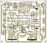
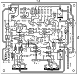
Hello everyone!
I corrected some mistakes that included my drawing pcb and I repost here for your opinion before going to production.
If everything is correct, I'll post the necessary files (. pdf) here for those interested here.
@ danielwritesbac:
You are the bible of Circlophone!
Thank you all.
Hello everyone!
I corrected some mistakes that included my drawing pcb and I repost here for your opinion before going to production.
If everything is correct, I'll post the necessary files (. pdf) here for those interested here.
@ danielwritesbac:
You are the bible of Circlophone!
Thank you all.
Attachments
Good thing about Darlington pcb is that it is easily adaptable to mosfet version without altering the layout. According to post #62 it is easily attainable by replacing 120R's with 390R. Darlington version was only exist on simulation but it is real for now. So why not for mosfet/hexfet?
Good idea!...I am thinking of the Latfets they seem to have more reputation than Hexfets when it comes to audio application. 2SK1058?

Good thing about Darlington pcb is that it is easily adaptable to mosfet version without altering the layout. According to post #62 it is easily attainable by replacing 120R's with 390R. Darlington version was only exist on simulation but it is real for now. So why not for mosfet/hexfet?
Lateral/Power fet outputs are very durable! The main limitation is thermal interface size, so if we used the TO-3PBL/TO-264-3 sizes, that could make high power Circlophone a reality. Fascinating!
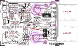
I modified my Darlington PCB layout for a possible higher wattage build.
* All transistors are Japanese type
* Traces are more 45 degree friendly
* Negative feedback cap should sit on plate now
* Input LTP face to faced
* Traces thickened a bit
I actually tried MN2488 (from Ebay) for myself but I'm not sure they were counterfeit or not. I don't remember that I have tested it with o'scope. I just listened and they worked just fine.
Servo transistors are that I listed are not that known type I know. They are not extinct and their specs are fascinating.
Any opinion are welcome.
Attachments
Last edited:
- Home
- Amplifiers
- Solid State
- Building Elvee's Circlophone: Documentation, Parts, Accessories, & beginner friendly