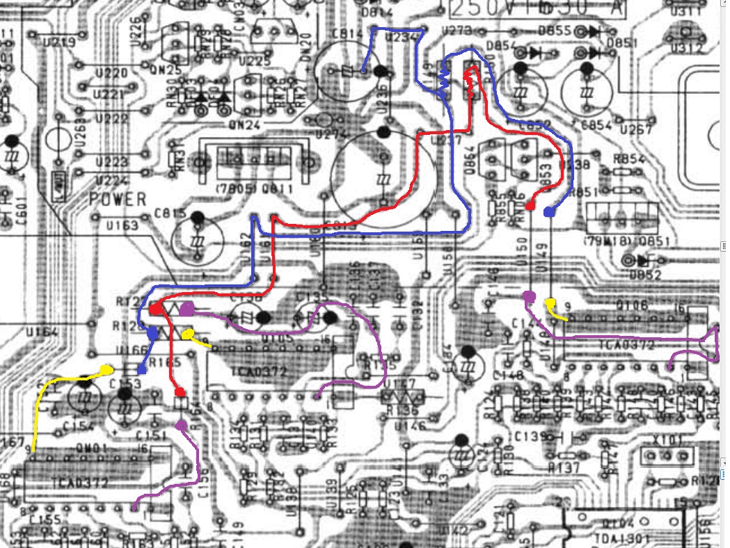
What you should do is firstly disconnect the stock Tx's connections from U308, U309 and U310. This will isolate the supply from the stock TX to the digital rail.I ve got the Tx but I'm not sure how to install it properly. It's this one:
http://www.amplimo.nl/images/downloads/ds standardrange/18612.pdf
Do I connect them parallel? Red + blue on U308 and yellow + grey on U310. Where do I get de earth from? I don't need a fuse before the Tx, do I?
Do I have to change the C813 cap (22.000uf Pan. TSUP 16V) to a 25V type, or will this work fine?
Use your newly purchase toroidal Tx, connect the RED cable to U308, then connect the YELLOW and BLUE cable together and connect them to U309 which is the GROUND. Lastly connect the GREY cable to U310 and the job is done.
I suggest you keep the 2 fuses at this moment until everything works okay and then you can bypass the 2 fuses in case something gone wrong.
After you have fitted the new 12Vx2 TX you will get about 18V DC at the digital rail and therefore you need to change C813 and C814 to 25V caps.
Here's this week's tweak ")
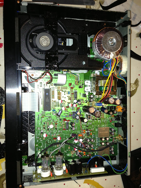
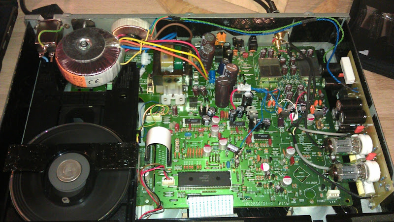
I've added a 50va 2 x 12v toroidal transformer and fully damped the chassis with car deadening panels. Thanks to people here for the helpful information. Here's some pics which might help someone else
This is the transformer I chose.
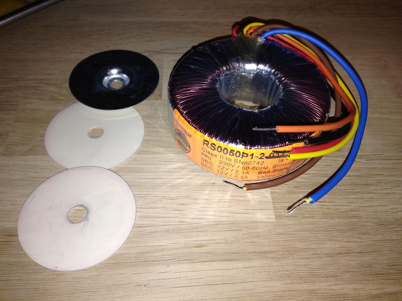
Because I don't use the standard output stage on my player, I'm keeping the standard transformer in place and just using this new toroidal to replace the 2 x 9.6v feeds from it.
So I made a little bracket from some stainless steel.
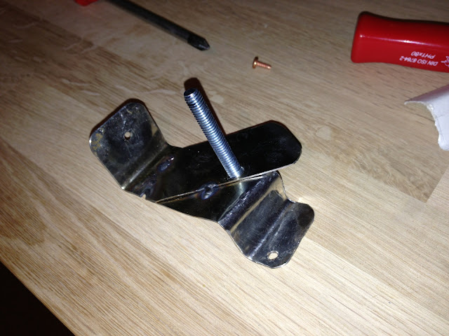
Test fit here.
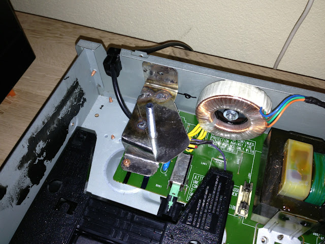
Only just clears the CD drawer
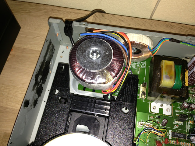
I've taken the input power to the primary winding from here
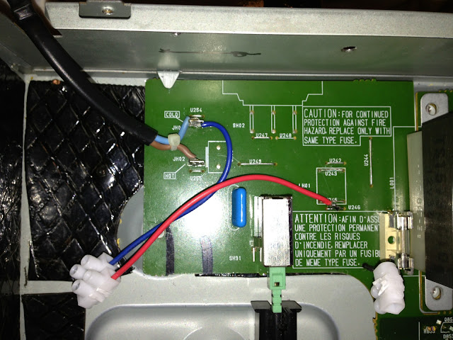
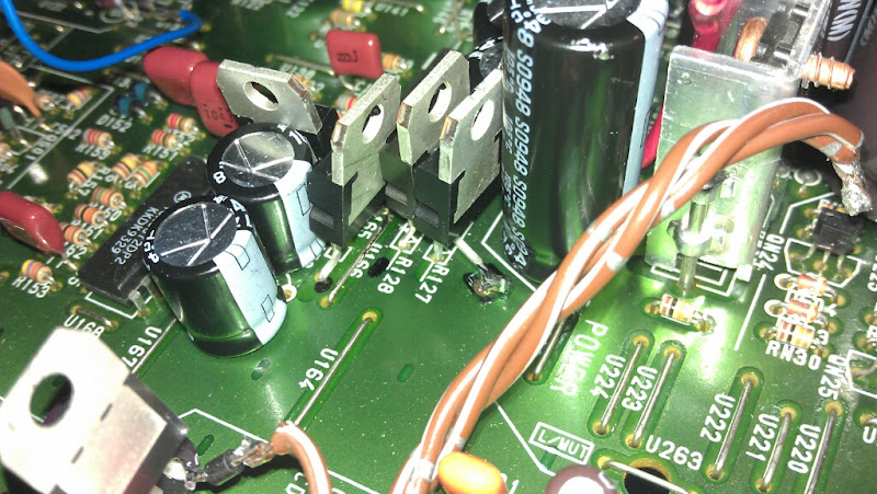
And replaced the existing fuse holders with these little PCB mounted terminal blocks. Existing holes are the outside 2 and I drilled new holes for the inside 2 which neatly sit directly either side of the ground trace from U309, so I scraped the track back inbetween and soldered the middle 2 directly to that.

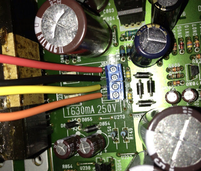
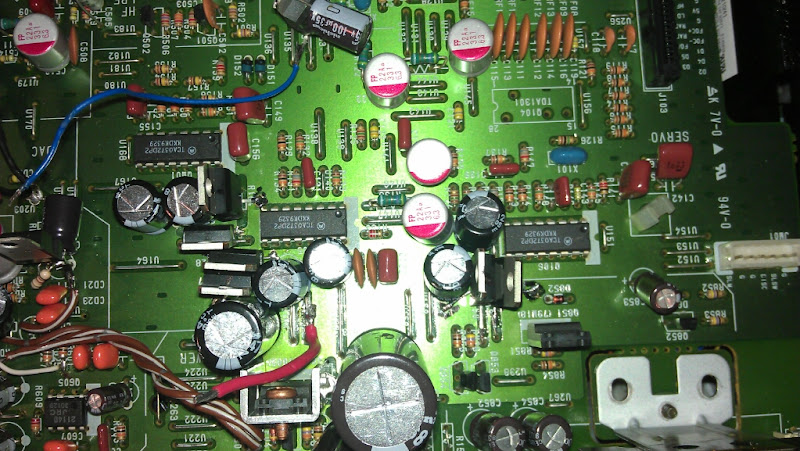
You can see here where I replaced C813, C814 and CN01 with 25v versions to cope with the higher 18-19v DC. I had fitted a 22,000uf TSUP cap on C813 previously, but I forgot it was a 16v so it needed changing. For now I've used 2 x 6800uf 25v Nichicon PW for C813 and C814, which have decent specs and were just what I have kicking about. I might change the C813 out for something larger later, am I right to think that's a little less critical with my new, beefy transformer?
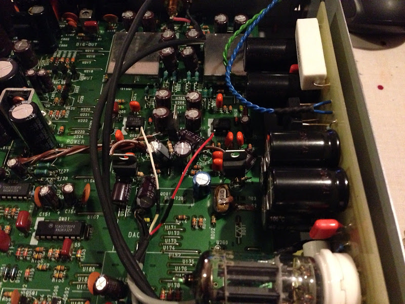
Anyway.. secondaries wired in.
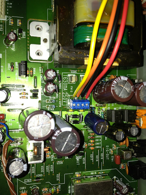
And here's how we're looking now
How does it sound? Well good and bad... It's all linked in fine and music plays nicely with no smoke or explosions, but I have a nasty humming buzz coming from the new transformer.
It sounds quite a mechanical buzz which makes a noise about the same as a 25hz square wave tone (no scope, but I have a tone generator)
You can hear it from about a foot away with the lid off and just about make it out through the heavily damped lid with your ear almost on it. I wouldn't mind quite so much, but it has also bled through every so slightly to the audio signal and whilst it's not intrusive, I can just about hear it through my speakers on quiet sections when playing loud
I'm going to try swapping the wires to the primary winding as I read that worked for someone else. I'm 99% sure that doesn't effect the polarity of the secondaries, but if someone could confirm, that'd be nice?
I might also try swapping the secondaries pairs over, but both of these are kinda hopeful stabs in the dark....
Hopefully I don't have horrible DC offset on my home AC, but I guess it's possible.... I did a quick google and found lots of people with similar sounding issues with Toroidals and no simple answers
I've added a 50va 2 x 12v toroidal transformer and fully damped the chassis with car deadening panels. Thanks to people here for the helpful information. Here's some pics which might help someone else
This is the transformer I chose.
Because I don't use the standard output stage on my player, I'm keeping the standard transformer in place and just using this new toroidal to replace the 2 x 9.6v feeds from it.
So I made a little bracket from some stainless steel.
Test fit here.
Only just clears the CD drawer
I've taken the input power to the primary winding from here
And replaced the existing fuse holders with these little PCB mounted terminal blocks. Existing holes are the outside 2 and I drilled new holes for the inside 2 which neatly sit directly either side of the ground trace from U309, so I scraped the track back inbetween and soldered the middle 2 directly to that.
You can see here where I replaced C813, C814 and CN01 with 25v versions to cope with the higher 18-19v DC. I had fitted a 22,000uf TSUP cap on C813 previously, but I forgot it was a 16v so it needed changing. For now I've used 2 x 6800uf 25v Nichicon PW for C813 and C814, which have decent specs and were just what I have kicking about. I might change the C813 out for something larger later, am I right to think that's a little less critical with my new, beefy transformer?
Anyway.. secondaries wired in.
And here's how we're looking now
How does it sound? Well good and bad... It's all linked in fine and music plays nicely with no smoke or explosions, but I have a nasty humming buzz coming from the new transformer.
It sounds quite a mechanical buzz which makes a noise about the same as a 25hz square wave tone (no scope, but I have a tone generator)
You can hear it from about a foot away with the lid off and just about make it out through the heavily damped lid with your ear almost on it. I wouldn't mind quite so much, but it has also bled through every so slightly to the audio signal and whilst it's not intrusive, I can just about hear it through my speakers on quiet sections when playing loud
I'm going to try swapping the wires to the primary winding as I read that worked for someone else. I'm 99% sure that doesn't effect the polarity of the secondaries, but if someone could confirm, that'd be nice?
I might also try swapping the secondaries pairs over, but both of these are kinda hopeful stabs in the dark....
Hopefully I don't have horrible DC offset on my home AC, but I guess it's possible.... I did a quick google and found lots of people with similar sounding issues with Toroidals and no simple answers
Last edited:
Recommended Toroids for Players in the USA?
I beleive I will replace the main transformer in my player with a toroid.
- Is there one that is recommended for use with 120Volts?
- I will also need advice on one to use with my flea which requires a DC voltage between 18 and 32 volts. Any thoughts? Perhaps a 15Vac secondary??? Any recommendations of where to get one of these in the US?
Regards,
Jerry
BIG TX and BIG smoothing caps are highly recommended, in particular, for the servo supply. This will ensure there is no fluctuation of voltage when the CD drive is run as it draws current on starting up and during operation. I have used a scope to measure the transient voltage dip and it can go down by 4-5V in milli of a second when the stock TX is used. With a BIG TX and caps the transient dip will be less than 0.5V and with very steady supply voltage all the time to the servo circuits. What you will get at the end of the day with a BIG TX and BIG smoothing caps is very tight and extended bass.
To my knowledge the servo circuit design of CD67 is better than CD63 as it is regulated but I still think BIG Tx and caps will certainly help. You are right there is only one clock of 16.xxx MHz for both DAC and servo circuit which is different form CD63 which uses two separate clcoks (16.xxx and 8.xxx MHz).
But that would put one of the Vsec outputs from the new tx to the ground on my boardActually after reading the label on the transformer, Black and yellow should be tied together for 0Volts so switch yellow and orange around.
Here's the datasheet for my tx:
http://docs-europe.electrocomponents.com/webdocs/0027/0900766b80027b3e.pdf

Orange and Black are 0v, so I connected those to the centre 2 connections, which are essentially U309 ground.

One thing that's probably not related, but comes to mind is that whilst I've removed the 2 x 9.6v AC supplies from the standard tx to the board by virtue of removing the fuses, I've left the ground for that winding in place. Will that matter or make any difference to anything?
But that would put one of the Vsec outputs from the new tx to the ground on my board
Yes, that is supposed to be the case. You're creating a symmetrical supply here, with + en - 10V voltages. The 0 and Vsec label is only there to indicate the phase of the winding.
http://wiringcircuitdiagram.wiringd...es/8/2008/08/basic_symmetric_power_supply.gif
Yesssssssss!Actually after reading the label on the transformer, Black and yellow should be tied together for 0Volts so switch yellow and orange around.

I swapped that pair around and the tx is now totally silent
And, I listened again and wow! what a difference the new power supply has made now that it's wired in properly...
I've only had a quick listen to it, but the bass is definitely more rounded and effortless and the imaging seems nicer too.
Happy days!
cheers guys
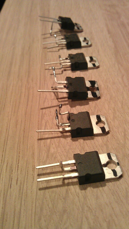
So tonight I've added 3 x 7809 and 3 x 7909 regulators to the 3 servo driver ICs.And it'll be even better if you regulate the new rails


This was using +/-8v from the original transformer, but you can use +/-12v regs if you are using a separate transformer and power supply.
I was going to just add one of each onto U234 and U237 and feed all 3 ICs from 1 pair of regs until I realised that you can't really get to these jumpers properly if you have large C813 C814 caps...

So I followed the pics above plus the excellent diagram here:
Here's the regs all bent up with the grounds tinned and ready for fitting
So I put them in like this
this
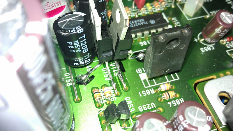
and this
Sorted?
Well it fired up fine nicely and sounded good, but I measured the voltages at pin2 of each of the driver ICs and 2 of them showed 9v at pin 2 whilst the middle one was still at 18v. So I went back to the schematics and did a bit of head scratching and it seems that these 2 regs have the input and output the wrong way around.

I can see how it's been done as I'm forever getting caught out by the fact that the schematic's a mirror opposite when you're viewing the board from above.
So I swapped those 2 regs to be round the other way:

And now it's allllll goooooood
Stable +&- 9v voltages at all 3 of the servo driver ICs.
I tidied up some of the wiring for the 5v regs and fitted a filtered EIC mains socket while I was at it. I also replaced the resistors R149 and R150 with wire jumpers too.
It's sounding real nice now. Smooth, powerful, well rounded and with excellent imaging and wonderful detail
Hopefully the pics above are helpful to someone aiming to do the same.
Next on the cards is some loving from Ray.... I've got a Flea with XO for the DAC and decoder as I'm currently using the standard clock and oscillator, but with Martin Clark's mods. I've also ordered a DOS board. I'm going to try using the filter and differential summing part of Ray's DOS board, but just after that, before it goes to the last output transistor, divert out and use my valve output stage instead. It should be a wonderful partnership. Can't wait to find out...
James
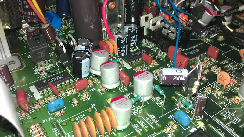
Thanks, yes, I'm currently using 3 x 7805 for the DAC with a smoothing cap on the input and a small resistor on the output to ensure good regulation even with these small loads. You can see in this crappy picture here:Good work James
Have you thought of providing stable power supply to the DAC and decoder in additional to the servo ICs ? That will boost the performance to another level if you use low jitter external clocks to the servo and the DAC.
It's messy and I've been meaning to tidy them up for a while.
I was planning to put 2 more 7805 to the decoder, but then I thought maybe I would use LT1763 regs for all instead and make a little power supply board like others have done, but then I was a little concerned about having the regulation far away from the load and running it over long(ish) wires. I don't really know the best approach....
Obviously the best method is to use a load of Spower regs or similar, but I don't want to spend the money

Does a clock for the servo really make a big difference? Even with good power and regulation like I have now?
I might see if adding a divider circuit to the new clock for the dac and decoder degrades the clock output significantly.
Nice job!
Your XO has been ordered
Ray
Excellent, thanks
OH trust me, a decent low jitter clock makes a lot of difference to the SQ of your CD63.
From my experience the improvement is most noticeable by changing the stock TX with bigger VA transformers + BIG smoothing caps; then by changing the low jitter clocks; and follow by putting in low noise voltage regulators + good quality low and high filtering caps.
From my experience the improvement is most noticeable by changing the stock TX with bigger VA transformers + BIG smoothing caps; then by changing the low jitter clocks; and follow by putting in low noise voltage regulators + good quality low and high filtering caps.
Thanks. I know the DAC and decoder will benefit a lot from a low jitter clock as the sound is much improved with just the Martin Clark mods to the standard clock.OH trust me, a decent low jitter clock makes a lot of difference to the SQ of your CD63.
But I would like to know if adding a low jitter clock to the servo as well will make that much of an audible difference?
Thanks. I know the DAC and decoder will benefit a lot from a low jitter clock as the sound is much improved with just the Martin Clark mods to the standard clock.
But I would like to know if adding a low jitter clock to the servo as well will make that much of an audible difference?
Yes definitely. I used two separate clocks in my CD63
Some clocks do have a flip flop frequency divider but I prefer using two separate clocks, a 8.xx MHz for the servo and a 16.xx Mhz for the DAC and decoder.
- Home
- Source & Line
- Digital Source
- Marantz CD63 & CD67 mods list