You won't see much difference in terms of voltage stability as such.......
You will see a difference in noise on the regulated supply.
You will definitely hear the difference a compliment of decent regs make")
On a different note, what's in your avatar pic?
Reminds me a bit of my old quads!!
You will see a difference in noise on the regulated supply.
You will definitely hear the difference a compliment of decent regs make
On a different note, what's in your avatar pic?
Reminds me a bit of my old quads!!
An externally hosted image should be here but it was not working when we last tested it.
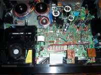
so, I've had a look today at the voltages in my machine and run some simple tests using my multimeter.
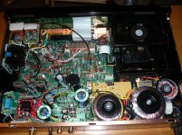
I know people like pictures, so here's a picture of some measuring happening:

No particular dig at anyone here, but I've read a huge load of this massive thread and I've seen a huge load of "improved bass", "better definition" & "brought new details to life I've never heard before" but very little actual measured or tested data. I know you can't measure everything and some kit is specialised and expensive, but some things can be looked at quite simply and without cost.
In my machine currently (standard non-SE cd63), I have a 22,000uf tsup C813 (positive 10v), and a 4700uf C814 (negative 10v) as well as basic upgrades to most of the smaller electrolytics.
I'm looking at power supply, specifically on the 10v rails too see whether I need a large 50va toroidal transformer or whether the standard one is adequate given the larger bulk capacitors on the rails as well as some additional voltage regulation further down the line. I was also basing this requirement on the fact that it has been mentioned about as much as a 4v drop at times with the standard kit.
The first thing I found was that just after pressing play, when the motor first spins up, there is almost a 2v drop for 1-2 seconds as the disc accelerates, but after that it becomes relatively stable. I don't really mind about that first second or so as there's no musical output at that point anyway.
what I measured over a couple of hours playing was:
Idling voltage on the +10v rail with the unit on, but doing nothing, was 11.58v and very stable.
during regular playing I saw:
Max
11.27v
Min
10.96v
on the +10v rail
And on the -10v rail.
Min
-11.57v
Max
-11.95v
Measured right at one of the driver ICs, taking the reading from the IC end of the ceramic cap C137 I saw min +10.63v, max +10.90v
voltages measured at the 3 parts of the dac and the display IC which I've fed using 7805 regulators fed from the 10v+ rail were all +5.00v bang on, totally stable.
What this says to me is I can stick to the standard power supply, but I should regulate the driver ICs, and 8V regulators seem like a good call there as I can guarantee more than 2.5v dropout during normal operation. A few more simple 5v regulators to other parts wouldn't hurt either as they're obviously effective.
Does that sound about right?
It is a good try but I am afraid that the voltage you see from your digital meter is not a true reflection of the transient voltages bearing in mind that the fluctuation of the voltages are in milli of a second and there is no way that your meter can show this fast changes. What you see in the meter is just an "average" reading. A stable low noise regulated supply will certainly make a lot of difference to the SQ. This can only be achieved by a BIG TX, BIG caps and good quality regulators. At the end of the day it is your ears to tell you the difference.
Last edited:
Hey everyone,
Thanks to Ray who I emailed a lot, I've started modding my CD57.
I've followed his guide ( http://www.raylectronics.nl/pdfs/CD57_mods_I.pdf )
Yesterday I did : opamps, output filter, power supply and servo pcb.
The flea (and its psu) is waiting for mounting material.
I will do the next (Dac, drivers, µcontroller and decoder) asap, but I'm already enjoying my cdp way more than before.
Thanks again guys
I guess my simple tests are far too simple for the subtleties of the high tech audio world...
I might get a simple scope and see what I can see, this one looks good for the little money it costs:
4 Channel USB Oscilloscope & Datalogger | eBay
I'm just using simple 78xx regs for now and I'm still pleasantly surprised at what a difference it makes.
I'll get a 50va toroidal ordered, are they all about 80mm diameter?
That picture's not one of mine sadly... but yes, KT88s in a Traynor YBA200 amplifier. I just love the magical glow of the image.
Here's a larger version you can almost warm your hands off
Evening
I've got my ic driver caps to fit now and I've made some jumpered fuses to replace the 630ma ones as well as fitting a 2,200pf polystyrene cap in c505.
Sound seems clearer again with a nice powerful yet supple quality to the bass
I've been comparing where I'm up to with a few pics from other people and I can see a pale blue rectangular cap used for c506 by the decoder, but I don't see it on any spec lists, can anyone enlighten me please?
Here's one of Ray's pics

Next up is the 50va toroidal, some regs for the driver ICs and an attempt to try and filter out some more of the dac noise.
I've got my ic driver caps to fit now and I've made some jumpered fuses to replace the 630ma ones as well as fitting a 2,200pf polystyrene cap in c505.
Sound seems clearer again with a nice powerful yet supple quality to the bass
I've been comparing where I'm up to with a few pics from other people and I can see a pale blue rectangular cap used for c506 by the decoder, but I don't see it on any spec lists, can anyone enlighten me please?
Here's one of Ray's pics
Next up is the 50va toroidal, some regs for the driver ICs and an attempt to try and filter out some more of the dac noise.
Last edited:
That blue cap is C506. I think it's a 330nF ceramic in the original player (can anyone confirm that?). It forms a low-pass filter for the decoder with R510. I replaced it with a 270n MKT that I had left. The SAA7345 schematic shows a 100n there, so I figured the value isn't too critical. Since an MKT has a better characteristic than a ceramic, it won't hurt to replace it. I'll add it to the CD63's mods lists!
Apparently, my pictures are studies very seriously
Ray
Apparently, my pictures are studies very seriously
Ray
Last edited:
Thanks Ray
I noticed Ian made the same change in a player he sold recently,

but neither of you mentioned it in your modification lists so I wondered what the secret was
And yes, I try to study as much as possible to keep my stupid questions to a minimum
Thanks for putting all your information together, it's been hugely helpful for me.
Infact last night I was reading your information about putting the extra capacitor between LO and LON & RO and RON in the filter section just after the dac and I wonder if that will still reduce the noise I was bothered about even if I only use half of the output for my valve stage. I'll order some caps and give it a go.
I noticed Ian made the same change in a player he sold recently,
but neither of you mentioned it in your modification lists so I wondered what the secret was
And yes, I try to study as much as possible to keep my stupid questions to a minimum
Thanks for putting all your information together, it's been hugely helpful for me.
Infact last night I was reading your information about putting the extra capacitor between LO and LON & RO and RON in the filter section just after the dac and I wonder if that will still reduce the noise I was bothered about even if I only use half of the output for my valve stage. I'll order some caps and give it a go.
Looking for help in repairing my CD63 tray problem. Each time I press the tray open/close button (and even by using the remote open/close button), the tray comes out half way and then goes back in again. I don't even have the chance to put a CD into the tray. Sometimes the tray comes out fully, and I can put in a CD for listening. But the problem starts again when I want to remove the disc. Pressing the open/close tray will cause the tray to come out halfway and then goes in for no reason.
Any particular component that might be causing this problem? I've tried changing the belting, but the problem is still there.
Ron.
Have a same problem. The problem was in micro switch under plate (see picture).This switch is for open-close tray motor.There is two wires (I think white and green).Throw small hole you will see some copper (electro contacts).Put some alcohol (cd cleaner,lens cleaner etc) and blow with straw (few times) .When alcohol evaporate put some WD40 BUT NOT DIRECTLY.Put some wd40 in small plastic glass then use toothpick to put liquid on the contacts.You can use some fine mechanic oil and use toothpick.
Ok, I checked it out in the CD63 service manual and it appears C506 is already a polyester film cap originally (a brown one IIRC), so there's not much gain to be expected by changing it. That's why it's not in the mods lists
Ray
Cool, thanks
CD-67 - Burson clock and OP AMP replacement
Hi all,
I am modding my first CD player (CD-67SE) and have it torn down to bare bones having installed damping material. I would like to install a Burson clock and replace the output op amps with something better.
- could someone please send me a schematic/SM?
- let me know if you have installed the Burson clock and what freq to get. 16.9344?
- Recommended OP amp replacement for the 21140 JRC chips. I plan to install sockets.
Thanks,
Jerry
Hmm, it's been a while but the TOP ones should include:
* servo re-clock
* DAC re-clock
* servo driver IC regulators (x6), preferably fed from their own transformer / PSU
* output op-amps
* DC blocking output caps bypass
Do these 5 and you will have a KILLER machine.
Simon
Hi all,
I am modding my first CD player (CD-67SE) and have it torn down to bare bones having installed damping material. I would like to install a Burson clock and replace the output op amps with something better.
- could someone please send me a schematic/SM?
- let me know if you have installed the Burson clock and what freq to get. 16.9344?
- Recommended OP amp replacement for the 21140 JRC chips. I plan to install sockets.
Thanks,
Jerry
I suggest you go through Ray's web page and you will find all the information you need. Ray's Audio Page
As to the opamp you can replace the stock one with LM4562NA or HA. HA is CAN type with better performance that I would recommend. Alternatively you can try discrete opamps like Bursons or Ray's DOS. They are even better than LM4562HA IMHO.
For the clock I recommend you to try Ray's clock as it is really GOOD and cheaper than Burson.
I have bought a pair of opamps (OPA-SUN) and a clock (Type1 - TCXO) from this seller: http://www.audio-gd.com/Products-EN.htm The products are of HIGH quality and the delivery is quick using DHL (parcel arrives 5-7 days from place of order with good communication) that I would also recommend.
I have also tried a Korean clock with 16.9344MHz http://www.ebay.co.uk/itm/R-Clock-H...430?pt=LH_DefaultDomain_0&hash=item35c10518e6 The reasult is also very GOOD (the delivery took about 2 weeks by free registered delivery).
If you want to try top of the class low jitter clock try this http://www.ebay.co.uk/itm/C3-Premiu...dioHiFi_CDPlayerSeparates&hash=item3f150bc05b I have used one of this in my CD63 supplying low noise and stable clock signal to the servo and it is really really GOOD (but you need to pay a lot more !!)
Lastly if you want to try a cheap clock buy one of this http://www.ebay.co.uk/itm/1PPM-16-9...709&pid=100016&prg=1006&rk=4&sd=230871603430& The result is average and it took almost 3 weeks to arrive.
You may wonder how come I bought so many clocks. The answer is simple as I have modded four CD63 so far, 3 for my friends and I keep the best one using top of the class components.
Last edited:
My completed works
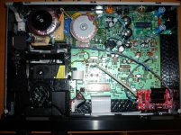
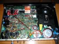
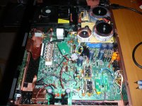
Further to the above, I have uploaded photos of my six completed projects for your reference Please note the different clocks and opamps I used. (Remark: After checking I found out that actually I have completed modding 6 CD63 rather than 4 as mentioned above)
Further to the above, I have uploaded photos of my six completed projects for your reference
Please note the different clocks and opamps I used. (Remark: After checking I found out that actually I have completed modding 6 CD63 rather than 4 as mentioned above)Attachments
Last edited:
Beautiful Work!
Very nice work and thank you for the response. I will read the info on the link you provided.
- looks like you changed the PS in all units you modified. Would you highly recommend this as well?
- since I have a 67 and not a 63 would this be quite different as I understand there is just one clock?
Thanks again, jerry
Hi Highlander.
Thanks for those pictures.
I'm wondering, how useful are the big caps (22000uf) you put in some of your mod ?
I guess 2 of them are C803 and C805, but which one are the others ?
What size do you think is the best suited for those caps ?
I've already changed them in my cd57 as suggested by Ray guide and I'm happy how it changed the SQ, but I've read many posts in this thread about larger ones, as you did.
I also have a few other question.
What's the aim of the rca connectors swap ?
How about the iec socket ? Possibility to use a better (at least shielded) main cable ?
DAC seems always reclocked, but what other component do you often also reclock. I dont understand why a cable is going near the servo zone. (I know my cd57 has a bit different pcb, but I should get a cd53 soon too )
Thanks for those pictures.
I'm wondering, how useful are the big caps (22000uf) you put in some of your mod ?
I guess 2 of them are C803 and C805, but which one are the others ?
What size do you think is the best suited for those caps ?
I've already changed them in my cd57 as suggested by Ray guide and I'm happy how it changed the SQ, but I've read many posts in this thread about larger ones, as you did.
I also have a few other question.
What's the aim of the rca connectors swap ?
How about the iec socket ? Possibility to use a better (at least shielded) main cable ?
DAC seems always reclocked, but what other component do you often also reclock. I dont understand why a cable is going near the servo zone. (I know my cd57 has a bit different pcb, but I should get a cd53 soon too
)BIG TX and BIG smoothing caps are highly recommended, in particular, for the servo supply. This will ensure there is no fluctuation of voltage when the CD drive is run as it draws current on starting up and during operation. I have used a scope to measure the transient voltage dip and it can go down by 4-5V in milli of a second when the stock TX is used. With a BIG TX and caps the transient dip will be less than 0.5V and with very steady supply voltage all the time to the servo circuits. What you will get at the end of the day with a BIG TX and BIG smoothing caps is very tight and extended bass.Very nice work and thank you for the response. I will read the info on the link you provided.
- looks like you changed the PS in all units you modified. Would you highly recommend this as well?
- since I have a 67 and not a 63 would this be quite different as I understand there is just one clock?
Thanks again, jerry
To my knowledge the servo circuit design of CD67 is better than CD63 as it is regulated but I still think BIG Tx and caps will certainly help. You are right there is only one clock of 16.xxx MHz for both DAC and servo circuit which is different form CD63 which uses two separate clcoks (16.xxx and 8.xxx MHz).
Hi Highlander.
Thanks for those pictures.
I'm wondering, how useful are the big caps (22000uf) you put in some of your mod ?
I guess 2 of them are C803 and C805, but which one are the others ?
What size do you think is the best suited for those caps ?
I've already changed them in my cd57 as suggested by Ray guide and I'm happy how it changed the SQ, but I've read many posts in this thread about larger ones, as you did.
I also have a few other question.
What's the aim of the rca connectors swap ?
How about the iec socket ? Possibility to use a better (at least shielded) main cable ?
DAC seems always reclocked, but what other component do you often also reclock. I dont understand why a cable is going near the servo zone. (I know my cd57 has a bit different pcb, but I should get a cd53 soon too
On the analogue rail I have changed C803 and C804 with 22000uF. And changed C805 and C806 with 1600uF.
On the digital rail I have changed C813 with 22000uF; C814 with 10000uF; and changed C815 with 6800uF.
(If you have space problem you can use 10000uF instead of 22000uF)
The purpose of Big caps is to ensure the supply voltages to the circuits are steady, in particular, if your Tx is small. Yes, don't forget to bypass the two fuses (for CD63) as they will restrict the current flow of the digital rail.
A good quality RCA socket can provide better contacts with your RCA cables.
Installing an IEC socket will enable you to change the power cables easily.
CD63 has two clocks. One for the DAC (and decoder) and the other to the servo. The cable you see near the servo is to supply 8.xxMhz clock signal to the servo circuit while the other two cables from the clock go to the DAC and the decoder. Most clock has a built in freq. splitter (divide the main freq. by half and a quarter etc). If you buy a 16 Mhz clock you may also get 8 Mhz output as well, however some clocks have only one single output and in that case you need to have two separate clocks if you want to clock the servo as well. If you look at my photos two out of my six CD63s have two clocks installed.
Last edited:
- Home
- Source & Line
- Digital Source
- Marantz CD63 & CD67 mods list