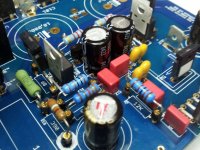
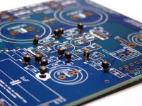
Here is a picture of a little socket forest. They are great for testing but there is an audible improvement after they are removed. You might find some leads to large to fit. Just use a super fine file to bring the diameter down. Do it in small increments as it's easy to go too far and end up with a sloppy fit. I also found it easier and safer to use small needle nose pliers near the end of the lead to insert in sockets and avoid bending and breaking resistor shells.
vox - There is no such thing as a silly or stupid question if you don't know the answer. I can't count the times I have asked about something basic and found others were wondering about the same thing. That's how we all learn so don't hold back.")
vox - There is no such thing as a silly or stupid question if you don't know the answer. I can't count the times I have asked about something basic and found others were wondering about the same thing. That's how we all learn so don't hold back.
Attachments
Last edited:
Here is a picture of a little socket forest.
Thanks Bob. That is a much better picture of sockets and how they work.
vox,
Ditto what Bob said about questions. I am far from expert. I've just been learning from these thread, especially this one, for about 9 months. Some topics are opinions with different points of view, many other are experience. Welcome to the club! I've had a lot of fun.
Jac
Okay I finished all the wiring. Tested with the light bulb setup, all is well. Tested offset, right channel 15mv left channel 40mv and drifting on to the listening test. Wired up a temporary pot, must have done it wrong didn't work right and has hum. Hooked up Yamaha integrated for use as a pre. Worked better but still hum. Source and pre off amp still has hum. Even with the hum the amp sounds good, lots of bass great soundstage........any thoughts
on to the listening test. Wired up a temporary pot, must have done it wrong didn't work right and has hum. Hooked up Yamaha integrated for use as a pre. Worked better but still hum. Source and pre off amp still has hum. Even with the hum the amp sounds good, lots of bass great soundstage........any thoughtsGet off my case Dario. I looked for the post where you excoriated me for the long leads when I posted that photo. At the time my FM radio wasn't working and I needed something to use to listen to my local college station.
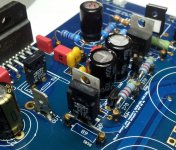
I found a few more pics that might be helpful.
I looked for the post where you excoriated me for the long leads when I posted that photo. At the time my FM radio wasn't working and I needed something to use to listen to my local college station. I found a few more pics that might be helpful.
Attachments
Worked better but still hum. Source and pre off amp still has hum. Even with the hum the amp sounds good, lots of bass great soundstage........any thoughts
Do you have a Walkman or phone with audio out to use as a source. That's what I use on initial tests - one channel at a time.
Tested offset, right channel 15mv left channel 40mv and drifting
Don't worry about that... after some hours of use it will drop to usual values (less than 10mV).
My last build started at 60mV and 125mV, after 10 hours of use it measured less than 5mV.
I suspect it's somewhat related to the flux.
Hooked up Yamaha integrated for use as a pre. Worked better but still hum. Source and pre off amp still has hum.
If there's hum it's probably a grounding issue, It happened on several builds, are you using Molex or soldered connections?
Speaker sensitivity?
You're using LM3386TF? If so is the heatsink grounded?
Even with the hum the amp sounds good, lots of bass great soundstage...
At the time my FM radio wasn't working and I needed something to use to listen to my local college station.
Dario, all of my conections are soldered except for the my input ground, I used the molex for these.
Yes I used the lm3886tf, the heatsinks are grounded to the rest of the enclosure, but I am not using the heatsink ground conection or the pgnd connection...I will add that I did connect the transformer shield to the chassis (antek as 3222)
thanks all for the help, sorry for the short play by play replies but I am out, but will be home soon
Hi everybody
could you tell me how is the gain of My-ref FE ?
I've found a nice active XO (SKA), but the gain is just less than 0. So, if the SPL of subwoofer and mid-tw aren't the same, I can't boost the subwoofer level but have to lower the SPL of mid-tw.
For example: mid-tw have 87db and subwoofer have 84db. In this case I have to lower mid-tw of 3db.
Do you you think that My-ref FE will work well with less input voltage, or it'is better to have a preamplifier (+6db) ?
Thanks !
marco
..........Tested offset.......... left channel 40mv and drifting...........
This sounds like using unreformed electrolytics that leak excessively............
My last build started at 60mV and 125mV, after 10 hours of use it measured less than 5mV.
I suspect it's somewhat related to the flux..........
Reform your electrolytics before fitting in critical parts of the circuit.
Hi everybody
could you tell me how is the gain of My-ref FE ?
I've found a nice active XO (SKA), but the gain is just less than 0. So, if the SPL of subwoofer and mid-tw aren't the same, I can't boost the subwoofer level but have to lower the SPL of mid-tw.
For example: mid-tw have 87db and subwoofer have 84db. In this case I have to lower mid-tw of 3db.
Do you you think that My-ref FE will work well with less input voltage, or it'is better to have a preamplifier (+6db) ?
Thanks !
marco
Hi Marco,
The gain of the MyRef FE is about 30 which turns out to be about 30 dB. That is on the high side for audio amplifiers, but not terribly unusual. I can't say if it will work as you hope, but it should. I have speakers in the mid-80 dB sensitivity and can play the FE using only a volume pot at roughly the 50% position.
Jac
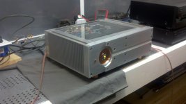
After a few unrelated early morning projects I was able to get back to the FE. I made a connection from each boards pgnd tab to safety earth and re connected the light bulb tester. With input and speakers disconnected I tested the offset. This time both channels were around 45mv and stable. Good. So on to a test with speakers. First was a pair of disposable infinity reference threes. Turn on was silent...amp on cd player at idle..total silence. Hit play on cd player adjust volume to 1/8 and wait. Slowly bon ivers Perth crept up out of the darkness. Eureka!
I quickly hit stop and shut off the amp, which aside from all three relays unlatching is silent. I connected an old pair of bose (I know) 201s for some better listening. Same thing dead black background very clear and refined bass, excellent separation, and detailed highs! I listened for a good forty minutes with a smile.
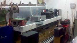
Its hard to tell from the pics below but that is Nathaniel Rateliff playing you should have seen the other guy in my garage/shop
I will hook all this up to my klipsch kg4s later and get some more impressions. And some better pics.
Thanks Dario, and all who contributed to this great amp
I quickly hit stop and shut off the amp, which aside from all three relays unlatching is silent. I connected an old pair of bose (I know) 201s for some better listening. Same thing dead black background very clear and refined bass, excellent separation, and detailed highs! I listened for a good forty minutes with a smile.
Its hard to tell from the pics below but that is Nathaniel Rateliff playing you should have seen the other guy in my garage/shop
I will hook all this up to my klipsch kg4s later and get some more impressions. And some better pics.
Thanks Dario, and all who contributed to this great amp
Attachments
Hi Marco,
The gain of the MyRef FE is about 30 which turns out to be about 30 dB. That is on the high side for audio amplifiers, but not terribly unusual. I can't say if it will work as you hope, but it should. I have speakers in the mid-80 dB sensitivity and can play the FE using only a volume pot at roughly the 50% position.
Jac
Thank you Jac !
This sounds like using unreformed electrolytics that leak excessively.
Reform your electrolytics before fitting in critical parts of the circuit.
Possible, but I've noted this strange behaviour also with all brand new caps.
I made a connection from each boards pgnd tab to safety earth and re connected the light bulb tester. With input and speakers disconnected I tested the offset. This time both channels were around 45mv and stable. Good.
The offset will go lower.
The fact that connecting PGND tabs to safety earth removed the hum confirm the presence of a grounding problem, IMHO.
All my builds are perfectly silent with PGND unconnected.
Same thing dead black background very clear and refined bass, excellent separation, and detailed highs! I listened for a good forty minutes with a smile.
I'm happy you're liking it.
Thanks Dario, and all who contributed to this great amp
You're welcome
Yeah Man!
This is getting exciting. We completed amps in the listening phase and some of us will be getting boards in the mail very soon. For those of you starting your build, I highly recommend reading or rereading the first 5 to 8 pages of this thread. Dario does a very nice walk through the build and answers lots of questions.
For those who are new to soldering SMD components, Dario offers some insight and there was a link somewhere to a video on how to solder SMD by hand. I just wish I could find that link.
Jac
Thanks guys,
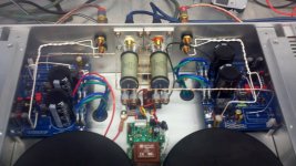
Dario, do you suspect a grounding error somewhere in the audio circuit or otherwise?
I did connect the toroids ground shield; I don't know if any other builders have used this toroid and can comment. In the build guide for the diyAudio store f5 the reader is instructed to not connect this. So maybe there is an issue with these that I have not encountered on the web.
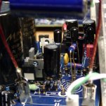
I attached a pic of the layout, it is a cell pic but you guys will get the idea. Im at a loss to figure out what error would be fixed by connecting the pgnd. The sound is perfect, is this somthing I need to fix..hmmmm.
Do other MyRef designs connect to ground or do they "float"?
Dario, do you suspect a grounding error somewhere in the audio circuit or otherwise?
I did connect the toroids ground shield; I don't know if any other builders have used this toroid and can comment. In the build guide for the diyAudio store f5 the reader is instructed to not connect this. So maybe there is an issue with these that I have not encountered on the web.
I attached a pic of the layout, it is a cell pic but you guys will get the idea. Im at a loss to figure out what error would be fixed by connecting the pgnd. The sound is perfect, is this somthing I need to fix..hmmmm.
Do other MyRef designs connect to ground or do they "float"?
Attachments
Last edited:
- Status
- This old topic is closed. If you want to reopen this topic, contact a moderator using the "Report Post" button.
- Home
- Amplifiers
- Chip Amps
- My_Ref Fremen Edition RC - Build thread