CFB
I haven't read it.
Hi Stein,
You're right about the definition of "current-feedback" in old school text books. But nowadays it makes little sense to stubbornly adhere to the old definitions. The paper below differentiates between four basic FB topologies:
1. Series-shunt
2. Shunt-series
3. Series-series
4. Shunt-shunt
I think this nomenclature is less confusing.
Cheers,
E.
Edmond
I could have mentioned both tanh and multi-tanh, but as I see it Mikeks is not interested in any technical discussion, his agenda is to try to prove that the CFA is useless for audio and is a compromised version of the VFA (which is not right).
I haven't read it.
BTW: Jan (and Mikeks) is right about the definition of "current-feedback" in control theory. I remember it from when I studied control theory back in the seventies.
BTW2: There are other IPS than LTP in VFA's, my preferred VFA IPS is H-bridge, best of both worlds.
Stein
Hi Stein,
You're right about the definition of "current-feedback" in old school text books. But nowadays it makes little sense to stubbornly adhere to the old definitions. The paper below differentiates between four basic FB topologies:
1. Series-shunt
2. Shunt-series
3. Series-series
4. Shunt-shunt
I think this nomenclature is less confusing.
Cheers,
E.
Attachments
Current feedback, very low TIM, very high slew rate, out, offset unstable so need a servo,
...
You need more good things of current feedback, for me it sounds the best, fast high slew rate, stable except the offset this do walk when not a servo because of sensitivity for heat in parts current loop....?
So untrue, VSSA 1 mV DC stable without any servo, PSSR 100 dB.

A CFB input stage with proper dimensioned RE's is far more linear.
Cheers,
E.
Exactly.

How to lower distortion -
Ciruits which present devices with virtual ground low impedance nodes are now generally becoming labelled as current-mode circuits.
How to lower distortion ---
Fundamentaly, volts and currents are associated to electric charge. Driving charge into high Z nodes will result in large voltage excursion. While charge driven into low Z nodes will result in small voltage excursions.
Thx-RNMarsh
Last edited:
Let's make it clear -- current feedback amplifier or opamp, since in closed-loop, current is fed back (set by the value of Rf) from the low impedance output to the low impedance inverting input -- that is the CF opamp operates with voltage-sampling, current-feedback. And, gain is set by the R from the inverting input (emitter) to ground.
Thx-RNMarsh
My contention exactly.
")
The word current says enough, current feedback is on low impedance nodes and voltage feedback is high impedance nodes.
The impedance of a node to which the feedback is returned does not determine the type of feedback applied.
It's just extraordinary how difficult it is to make simple points of fact on this forum.

So untrue, VSSA 1 mV DC stable without any servo, PSSR 100 dB.
Afcourse with the better components these days and thermal coupling, matching yes it can be done,.
PSST 100 dB, it is simple these days also, components are of high quality, but if not done thermal coupling offset go run, however I have play a current feedback amp without servo some years ago, it did walk between 2 and 90 mv so that was oke, some audio junkies want 1 uV or so before she consider there amp high end.
A servo is a nice tool get amp balanced, I have now a double mu stage hybride and this have current feedback to the first tube cathode, and yes this need a servo who act also as a tube age corrector.
Current feedback make the amp bandwith go in the megaherz sometimes so a taming is needed otherwise we have a receiver sometimes..
I am not as a calculating man, I make combinations with amps and a simulator.
Nice schematics from marsh, I did use this as a amp in a amplifier a la Alexander with the discrete opamp like marse but come not further the simulating.
For current feedback, it because of the low impedance node, make voltage a current, and if node is high impedance it get voltage, if I read internet it seems that
much people don,t understand current feedback, honestly I do also not now all, only that it is wat the word say, currentfeedback and it makes the amp independent
of bandwidth of open loop, therefore you see this current feedback a lot in video opamps and such, even opamps for medical purposis like hartbeat amplifiers.
regards
Last edited:
Just being practicle now --
See first sentence of line #564 above, again -->
Unfortunately, right or wrong doesnt matter any more, others have decided what to call the topology and all IC makers use that meaning of the term. Its locked in now. In this case majority rules. So I call it by what many others now call it... current-mode feedback. Its just the explanation of how it works that you can aurgue but even that has been concluded and accepted by designers, engineers and manufacturers, alike. World wide.
Thx-RNMarsh
The impedance of a node to which the feedback is returned does not determine the type of feedback applied.
It's just extraordinary how difficult it is to make simple points of fact on this forum.
See first sentence of line #564 above, again -->
Unfortunately, right or wrong doesnt matter any more, others have decided what to call the topology and all IC makers use that meaning of the term. Its locked in now. In this case majority rules. So I call it by what many others now call it... current-mode feedback. Its just the explanation of how it works that you can aurgue but even that has been concluded and accepted by designers, engineers and manufacturers, alike. World wide.
Thx-RNMarsh
Last edited:
You should read the paper " HIGH SPEED OPERATIONAL AMPLIFIERS " by Walt Kester of Analog devices. The naming of the CFB topology has nothing to do with whether the feedback is a voltage or a current, it is the result of the feedback action which is the reason for the naming.
I have posted this before but seems no one read it. Here is the link, see page 14, first paragraph. This is what I was taught in university so there s no mistaking it with feedback theory.
http://www.analog.com/static/imported-files/seminars_webcasts/36692482463115527495427664003sect1.pdf
The text on page 14 says: "Feedback from the output to the invering input acts to force the inverting input current to zero, hence the term current feedback"
This is completely untrue. The input stage is a push-pull class AB complimentary arrangement that will either source current to or sink current from the feedback network regardless of the feedback and dependent on the polarity of the input voltage.
In other words, the feedback doesn't act to " force the inverting input current to zero..."
Rather, completely consistent with orthodox feedback control theory, the voltage divider that is the feedback network, connected in parallel with the output, drops a fraction of the output voltage across the inverting input. This is then subtracted from the input voltage to produce the error signal which drives the amplifier's forward path.
Last edited:
....While charge driven into low Z nodes will result in small voltage excursions.
Thx-RNMarsh
Not true necessarily: the voltage developed depends on the current supplied to the node, regardless of its impedance.
-- that is the CF opamp operates with voltage-sampling, current-feedback.....
There is no such thing as "voltage sampling current feedback".
The nearest thing to what you've described is shunt (voltage) derived-shunt (current) applied negative feedback or transimpedance feedback.
However, I am positive that what you're really refering to is shunt (voltage) derived-series (voltage) applied negative feedback or voltage feedback. This should never be described as current feedback.
See first sentence of line #564 above, again -->
Unfortunately, right or wrong doesnt matter any more, others have decided what to call the topology and all IC makers use that meaning of the term. Its locked in now. In this case majority rules. So I call it by what many others now call it... current-mode feedback. Its just the explanation of how it works that you can aurgue but even that has been concluded and accepted by designers, engineers and manufacturers, alike. World wide.
Thx-RNMarsh
The truth is sacrosanct regardless of whether others choose to believe a lie.
Last edited:
The same questions are asked of app engineers such as Erik Barnes of Analog Devices in a column called Ask the Applications Engineer -#22.
I would refer interested parties to read his answere and comment to him.
www.analog.com/library/analogDialog/Anniversary/22.html
Thx-RNMarsh
I would refer interested parties to read his answere and comment to him.
www.analog.com/library/analogDialog/Anniversary/22.html
Thx-RNMarsh
There is no such thing as "voltage sampling current feedback".
The nearest thing to what you've described is shunt (voltage) derived-shunt (current) applied negative feedback or transimpedance feedback.
However, I am positive that what you're really refering to is shunt (voltage) derived-series (voltage) applied negative feedback or voltage feedback. This should never be described as current feedback.
What if --- a voltage is 'sampled' and applied to a low/zero Z Ohm port?
If the port Z is virtual or not, the port Z behaves as if it was zero. Only current flows. Thus the name. You are making this WAY more complicated than it is. Who cares? ... shunt/series/voltage/current. The formulas for gain et al are different for the applications engineer.
The first paragraph of the web site refered to above says it about as clearly as it is going to get. The rest is important in describing the effective differences between VFB and CFB and the resulting differences.
Thx-RNMarsh
Last edited:
I did a search on this thread for tanh. Nothing!
Amazing that nobody mentioned it with regard to the LTP of a VFB input stage thus far. A CFB input stage with proper dimensioned RE's is far more linear.
Cheers,
E.
Edmond, why you don't use CFB in your amps then??
BR Damir
So untrue, VSSA 1 mV DC stable without any servo, PSSR 100 dB.
You never support your claim with any measurement or at least simulation.
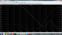
Here is my simulation of the VSSA PSSR.
BR Damir
Attachments
You never support your claim with any measurement or at least simulation.
Here is my simulation of the VSSA PSSR.
BR Damir
dadod and his simulations pics

Tell me in db what's the ratio betwween 1 Vrms and 10 uVrms. FLUKE doesn't lie, your sims worth nothing, total BS.
P.S. Output DC offset is stable at +1 mV
dadod and his simulations pics
Tell me in db what's the ratio betwween 1 Vrms and 10 uVrms. FLUKE doesn't lie, your sims worth nothing, total BS.
P.S. Output DC offset is stable at +1 mV
As I expected, no any argument accepted.
P.S. I don't say that this amp is not good, but you behave as a salesman.
As I expected, no any argument accepted.
P.S. I don't say that this amp is not good, but you behave as a salesman.
Well, I don't accept your cartoons, you don't accept reality measurements from FLUKE. Who's right?
Well, I don't accept your cartoons, you don't accept reality measurements from FLUKE. Who's right?
You could be more careful with words, for you cartoons, for others technical arguments.
By the way could you explain in more details how did you measure the PSSR with "FLUKE"?
- Status
- This old topic is closed. If you want to reopen this topic, contact a moderator using the "Report Post" button.
- Home
- Amplifiers
- Solid State
- Current feedback - Voltage feedback, how do I see the difference?