This is interesting :
http://www.en-genius.net/includes/files/tmt_1002.pdf
http://www.en-genius.net/includes/files/tmt_1002.pdf
After much head scratching and work done by Frans and me i decided for the balanced Paradise to go back to circuit 8440. The problem with the transimpedance solution is that i can not guaranty that a current flows into the cartridge. That is much easier to solve with the transconductance circuit 8440 and it does not need as much change to the original schematic. I also listened more and the transimpedance input, at last how i build it, makes the sound a little harsh. The improvements we made to the circuit also added complexity and did not give ideal noise performance ones we solved the peaking. To trim the offset again brings in more components. I do not say that it is not solvable but 8440 is the easy road and it sounds pretty decent.
One of the view investigations what happens when you connect a speaker to an amp :
http://www.linearaudio.nl/linearaudio.nl/images/pdf/amp-spkr interface.pdf
http://www.linearaudio.nl/linearaudio.nl/images/pdf/amp-spkr interface.pdf
This is interesting :
http://www.en-genius.net/includes/files/tmt_1002.pdf
Good morning to you
Yes it realy is tanks
I think the wort is that we tend to look at the voltage-performance and forget about the current, making the assumption that when voltage performance is good, then then current performance will follow. Fact is that the two are quite independent.. we tend to believe that low output impedance is the same as low current distortion.. I wonder how to get a good grasp and understanding on this...
I know, but to isolate the performance only to the magnet material is not terribly solid. There are more issues to dynamic magnetic flux variations when it comes to lsp motor designs. On top of that lays the dynamic acoustic foot print and compression left from the size of the magnet structure.
Most dynamic flux variations can be tamed by hysteresis rings, or by some crazy mean of a counter driven magnet structure. (ooops)
Most dynamic flux variations can be tamed by hysteresis rings, or by some crazy mean of a counter driven magnet structure. (ooops)
That is strange, my build is qiet.
question: was your build just the front end and then you used it as a head amp or you build the daughter board on the paradise?
Because Simulation of the entire circuit shows acceptable noise performance, but by any means not in pair with what you like and that is why I was wondering about that.
I will post the noise performance a little later...
ok.
Leet me plug the new circuit in and see how it looks like noise wise.
BTW with the same models I can get the paradise to be at least 3dB quiter thus I am not so sure that in this instance the noisefloor of the models is playing a big role but I might be wrong and in that case please point me out to the right model to use to have a more realistic result.
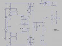
It depends of cause on the transistor models but the rise in the bass is not good.
Anyway, i do not want to make a balanced transimpedance input any more.
Lets go back to the older circuit.
Your master intuition was right.
The older circuit simulates just perfectly noise wise.
It looks extremely interesting and it could be made completely balanced from in to out.
I am wondering if enough gain can be reached with Jfets as well.
I will have to simulate this as well.
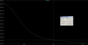
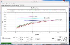
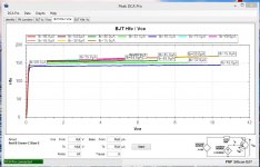
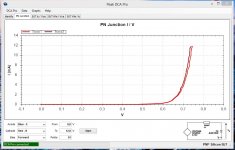
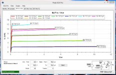
Today i istalled the new software for the DCA75 pro curve tracer. It adds some more functions. Here you see measuremets taken on a pair of Zetex medium power tranistors that are known to be low Rbb. What i find interesting is the curve Hfe over collector current. The PNP has full Hfe, even at very low idle.
Attachments
There is a lot of discussion about what amp is CFB or VFB on DIYAUDIO. Some theoreticians even went so far that a CFB amp does not exist and that it is a flawed VFB amp at best.
I watch this but do not comment much. The biggest discussion is if the correction signal is current or voltage. I think this is nearly impossible to answer. Pure current has zero voltage and pure voltage has zero current so it is always something in between. Also there is confusion about a current drive amp that has a high output impedance and CFB ( current feed back ) what is not the same. I learned that the topologies are differentiated by the open loop gain and the open loop bandwidth. VFB usually has very high gain at low frequencies and CFB usually has less gain but a wider open loop bandwidth. That has consequences how the different topologies have to be compensated. For example a CFB amp usually does not allow a cap to be placed in parallel with the feedback resistor or it gets unstable. What can be done in case of overshot is to place a passive low pass filter BEFORE the map.
Why do i mention this here ? Well, because Frans is coming up with a really innovative power amp and he had some issues to make it stable. So we had a rather long meeting on Frickelfest Light about if his amp is VFB or CFB. Stay tuned.
http://www.analog.com/static/imported-files/seminars_webcasts/36692482463115527495427664003sect1.pdf