...
the higher cpu usage, the worse playback quality.
...
heavy cpu load cause MMU busy then data latency gets bigger, affects jitter ...
That´s an urban legend, there is no data to support this and no mechanism which would
make this possible.
That´s an urban legend, there is no data to support this and no mechanism which would
make this possible.
not urban legend at all. we did test this 2 years ago, the whole model is much more complex than what you could image.
in the very beginning, I don't trust this like all the other ppl doubting this, but when you could hear the difference, the fact is there, you must find a way out to solve the problem.
No dogital engineering is digital engineering, sorry to disapoint you, yes we know how a square wave is made up, I would sugest you look up knee frequency and access some of the links in the text file I have added. Also I would reccomend some reading from the likes or Eric Bogatin and Howard Johnson just to name a few.
Shock horror CPU dosn't know the difference between data packets and dont give a dam, yes it may come as a shock but the DOS routine just gets data from the disk when requested, whereever that data may end up...
How does a device know whether a bit is a 0 or 1, comon you day your an engineer, its one of the basics of digital transmission... switching thresholds say below 0.6V for a zero 3.0-5.5V for a 1 (data from an actual device with 3.3 to 5V tolerenat input, works from 3.3V-5V) so when the timing signal says read the data, the levels present at input pins are read (think d-type to make life easier) and that determines the signal. Its not rocket science its digital engineering.
The audiophile dream of it all been analogue and attributing analogue techniques to digital (such as low level wideband noise) dosn't cut it.
The whole point os signal integrity simulation is to ensure that the data is geting toi the required place at the right time and with enough integrity to ensure thye correct level is determined every time. (Dont bother trying to confuse the issue by saying we use some analogue technigues such as S parameters, but we do,) the end result is digital. The faster the rise time of a signal the higher the spectral content of the digital wave, knee frequency will give a figure of the frequencies range we need to care about. The higher frequency content of a square wave is often first to get affected by transmission, hence you often get rounding of of the wave (this is much more prefferable than ringing on the wave), but this does not matter because its digital and as long as the rising edge or falling edge passes through the threshold levels the data will be passed intact....
Shock horror
CPU dosn't know the difference between data packets and dont give a dam, yes it may come as a shock but the DOS routine just gets data from the disk when requested, whereever that data may end up...How does a device know whether a bit is a 0 or 1, comon you day your an engineer, its one of the basics of digital transmission... switching thresholds say below 0.6V for a zero 3.0-5.5V for a 1 (data from an actual device with 3.3 to 5V tolerenat input, works from 3.3V-5V) so when the timing signal says read the data, the levels present at input pins are read (think d-type to make life easier) and that determines the signal. Its not rocket science its digital engineering.
The audiophile dream of it all been analogue and attributing analogue techniques to digital (such as low level wideband noise) dosn't cut it.
The whole point os signal integrity simulation is to ensure that the data is geting toi the required place at the right time and with enough integrity to ensure thye correct level is determined every time. (Dont bother trying to confuse the issue by saying we use some analogue technigues such as S parameters, but we do,) the end result is digital. The faster the rise time of a signal the higher the spectral content of the digital wave, knee frequency will give a figure of the frequencies range we need to care about. The higher frequency content of a square wave is often first to get affected by transmission, hence you often get rounding of of the wave (this is much more prefferable than ringing on the wave), but this does not matter because its digital and as long as the rising edge or falling edge passes through the threshold levels the data will be passed intact....
Attachments
... the whole model is much more complex than what you could image.
Ah and now comes the mysticism and esoteric knowledge...
Show us this test.
... the fact is there ...
Show us these "facts".
like still lots of people don't understand this simple explain
let me explain how data is transfer from SSD disk to i2s (say data is bit to bit identical)
OS read disk data (OS will use DMA by MMU), SSD controller will decode the address and send to related flash(another cpu), then collect the data and send back, before sending back data, encode data to physical layer, different portion of the data will cause slightly different access time, this will affect eye diagram, and after transfer to the cpu, decode data and send to DDR memory, DDR has refersh time, and MMU will accss many address according CPU's requests, access time is random, so who knows when your request could be real time(DDR refresh time and MMU access time). that comes jitter of data transfer. and at the same time, OS/display/audio/disk access will share the same memory, no data could be send out realtime like FPGA does, that's the basic theory of OS.
for cpu load affects jitter, that's analog problem
heavier cpu load, more current for switching capacitance, then more noise, noise affects the trigger voltage (in fact IC will have a trigger level, under 3.3V system the voltage should be 1.5V), when the main power supply changes, trigger voltage follows.
because high speed clock always shows like sine wave, so, stablilty of trigger voltage becoms important. clock jitter will accumulate because of this effect.
bigger jitter affects playback sound.
for digital part, jitter is one of the most important parameters, finally power supply affects.
for analog part, power supply is one of the most important parameters above all other parameters
There are so many things wrong with your explanation, it´s hard to decide where to start.
No you don´t need a real time OS. No it does not matter when or how fast the OS reads the audio data from disk and decodes it (even your old iPod is fast enough for that).
For the influence of the CPU load on the power supply (this is claimed sometimes, but no one has shown measurements so far that it would be sufficient to induce jitter): Then fix your power supply, or even better don´t use the clock of the source. (master clock is in the DAC like it has
been done in studio equipment for ages, or asynchronous USB comes to mind.)
Last edited:
There are so many things wrong with your explanation, it´s hard to decide where to start.
You owe me a drink!
WOW!
so confusing. Jitter is not transfered from one stage to another, evey buffer is a break in the data flow!
As to DDR memory interfaces well, how many DDR based memory interfaces have you worked on? or simulated?
Earlier you stated PCB layout could affect sound, please enlighten me on this, are we talking about the digital layout? or the final analogue section, or both!
Also how do digital cables affect sound, please note here I refer to cables that are engineered to do the job.
I do not think we have an engineer here; I dont claim to be one, but its pretty easy to see that powerpan seems to discount any and all of the error checking, buffering and rejection along the whole signal path from computer to DAC and mixing up the methods and problems for all; as well as throwing in a few fictional ones for good measure... do we have some hours on google studying for these posts, taken from some people who did not know what they were talking about?
I say again, we do not use the embedded clock, hell where IS this embedded clock? what type of stone-age USB audio connection are we talking about? nevermind that we were not talking about such matters, the claim was that 2 bitperfect files could produce different results, or images could look different depending on where on a disk they came from. often a single file will be pulled from sectors spread across the disk and SSD will often create multiple copies, particularly enterprise grade, so we can end up with samples in a 1khz pure tone being different if its pulled from SSD can we? its nonsensical! I guess wear-leveling must be a veritable panacea of jitter...
the comprehensiveness of the misunderstanding is quite an achievement
Last edited:
Ah and now comes the mysticism and esoteric knowledge...
Show us this test.
Show us these "facts".
the fact is: local playback is clearer than network playback
sd card is better then USB/SATA
more direct data route, better sound.
WOW!
so confusing. Jitter is not transfered from one stage to another, evey buffer is a break in the data flow!
As to DDR memory interfaces well, how many DDR based memory interfaces have you worked on? or simulated?
Earlier you stated PCB layout could affect sound, please enlighten me on this, are we talking about the digital layout? or the final analogue section, or both!
Also how do digital cables affect sound, please note here I refer to cables that are engineered to do the job.
in audio field, lots of unknown. I agree with you in theory, FIFO will stop jitter, but no matter how many flip-flops you are using, still original data will affect sound. that's not how DDR works issue, should concern with data path.
i2s data transfer by pcb layout, so, sound will be different. why some manufacturer use teflon PCB instead of FR4. so if there is no difference, why use teflon ?
Mark Levinson use teflon as sell point only?
Mark Levinson use teflon as sell point only?
Yes.
the fact is: local playback is clearer than network playback
sd card is better then USB/SATA
more direct data route, better sound.
hahaha you must have a different definition of the word fact than the rest of us...
Jeremythe claim was that 2 bitperfect files could produce different results, or images could look different depending on where on a disk they came from.
I did NOT say anything about images coming from the same disc.
The original image was derived from a .ts file saved on HDD. The 2nd image was derived from the .ts file after it was copied to a Corsair Voyager GT USB 2,0 memory stick powered by a very low noise +5V linear PSU. Both the + and - supply leads (red and black) were disconnected at the USB-A plug at the PC end and a 220 ohm resistor fitted across the + and - pins of the plug . This meant that there was no earth loop due to the screen of the USB memory being connected internally to the black 0Volts lead.
Did you see the message that I sent you ?
Alex
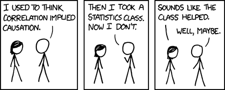
One of the issues that I believe further contributes to the confused state of 'understanding' in audiophiles is not just the misunderstanding/pseudo science/expectation bias etc. But a simple misapplication of basic statistics. That is, correlation does not necessarily imply causation.
xkcd: Correlation
xkcd: Correlation
Attachments

the fact is: local playback is clearer than network playback ...
So when I buy a high resolution audio file the sound quality will be
completely destroyed once I have it downloaded, right ?
Imagine it has to pass miles and miles of cable, routers switches ...
If there is a proxy, even worse, most of them don´t have a real time OS...
It might have the same checksum but this means nothing... the same
way as 2 + 2 = 5 for large values of 2, right ?
Sorry for the sarcasm, but such irrational claims provoke it.
@SY I think we should rather go for the drink I owe you, than wasting time
with this. ;-)
Last edited:
One of the issues that I believe further contributes to the confused state of 'understanding' in audiophiles is not just the misunderstanding/pseudo science/expectation bias etc.
And the Objective side doesn't suffer from "expectation bias" ?
Pigs might fly!!! They are far more likely to be affected by expectation bias due to their training. Many believe that they can look at their test equipment, and know EXACTLY how something is going to sound.
And the Objective side doesn't suffer from "expectation bias" ?
Pigs might fly!!! They are far more likely to be affected by expectation bias due to their training. Many believe that they can look at their test equipment, and know EXACTLY how something is going to sound.
When did objective become proper noun?
All humans are susceptible to expectation bias.
Teflon wont affect the sound, I2S is a digital transfer, the data gets there or it dosn't.
FR4 based PCB's are good into the GHz range of frequencies, what will affect the digital signal transmission is BAD layout, the main cause of this being a lack of understanding on how digital signals propogate down a wave guide (trace).
One question what does teflon affect in terms of digital signal transmission, and how would this affect the sound?
Er
- Status
- This old topic is closed. If you want to reopen this topic, contact a moderator using the "Report Post" button.
- Home
- Source & Line
- Digital Source
- DIY hifi source