Attacks ?
Seems to me you lack both a sense of humor, and communication skills.
"Max dissipation figure" is not the same as "dissipation", merely the total Pd of the devices.
What you are telling/thinking of doing is just throwing a lot of extra hardware to it, more capacitance, huge toroid VA numbers.
Jakarta Jay will gladly explain to you that designing is a total system approach.
Tandberg made a number of very well designed amps, shame they were so expensive then due to the NOK exchange rate.
But so did Goldmund, their amp designer is a smarter bloke than you give him credit for ("the flaws in the design of this project")
Seems that you're the uncomfortable one.
Have a nice evening.
Last edited:
According to the MM9.2 specification the amplifier have two transformer blocks that weighs 15 kg each / channel. I think they are using some large toroidal transformers or perhaps the specification is wrong ? One 2 kVA transformer weighs around 12 kg.
The total weight of one MM9.2 mono block is 65 kg.
Hope this helps
The total weight of one MM9.2 mono block is 65 kg.
Hope this helps
Attachments
Last edited:
According to the MM9.2 specification the amplifier have two transformer blocks that weighs 15 kg each / channel. I think they are using some large toroidal transformers or perhaps the specification is wrong ? One 2 kVA transformer weighs around 12 kg.
The total weight of one MM9.2 mono block is 65 kg.
Hope this helps
Looks to me as it is conventional transformers.
But I have no trouble believing in a total transformer-power in excess of 2KVA.
I am to use my amp in my livingroom, and I don't have enough power installed to go past 2,3KVA in total. If I decide to install a new powerline, it will be able to cope with at least 3,6KVA.
Anyone wondering why Goldmund installed so much "KVA"?
I'm not surprised.
I have two 2KVa trafos
getting very tired of them
dont know why they had to be so big and heavy
well, maybe I know
when
getting very tired of them
dont know why they had to be so big and heavy
well, maybe I know
Well the MM9.2 consumes max 1000W / channel from the mains according to the specification so you do not have to do that I think.
when
Attacks ?
Seems to me you lack both a sense of humor, and communication skills.
"Max dissipation figure" is not the same as "dissipation", merely the total Pd of the devices.
What you are telling/thinking of doing is just throwing a lot of extra hardware to it, more capacitance, huge toroid VA numbers.
Jakarta Jay will gladly explain to you that designing is a total system approach.
Tandberg made a number of very well designed amps, shame they were so expensive then due to the NOK exchange rate.
But so did Goldmund, their amp designer is a smarter bloke than you give him credit for ("the flaws in the design of this project")
Seems that you're the uncomfortable one.
Have a nice evening.
I am truly sorry if Your comments really was ment as humour.
Also I am not throwing around the extra capasitance and VA-numbers.
To explain why I bring it up, I will have to explain why I "need" all this capacitance and VA. OK?
My gual is that this amplifier should sound as good as possible, but unfortunately I have some limitations as I haven't installed enough electrical cables to handle the kind of power I actually would need to obtain the VA-numbers that really is needed for this amp to have electrical ressourses needed. I perhaps should put out some numbers to explain it?
My goal is to have this amp to be able to provide a continious power of 350W in 8 Ohms, and as close to 700W in 4 ohms as possible .
This is 53VAC into theese 8 Ohms, ending in 6,6 Amps.
For 4 Ohms it will be around 13,5 Amps.
This current need to origin from somewhere. The transformer(s) in the amplifier. The voltage I selected for this project differs about 10% from what Goldmund have used in this amp. The transformers deliver 2X55V.
Looking at the current again I find that I needed a transformer at least 725VA. As I found no suitable transformer at 725VA, I selected the 625VA transformers. My mistake was not to complete the calculations to be able to obtain theese 700W in 4 Ohm. With the transformers selected I only will be able to get around 170W in 4 Ohms. Quite far away from my goal.
The only way to obtain the 700W at 4 Ohms is "to throw in some more VA".
By adding a extra pair of 625VA-transformers I will be able to get close to 700W in 4 ohms. 676W is theoretical possible then. No headroom or other reserve to have that kind of power available.
This leads to the extra uF. Wonder why?
Well, music is luckily not as static as a testone to determine the power output versus distortion. But as the transformers only just is big enough for this project, I found it nessesary to turn to some extra capasitors to have room for some "overshoot" when needed. This have Goldmund made possible with even bigger transformers than I ever would have installed in my amplifier.
So my GMC is an amplifier built with some compromises.
I have less VA, but some more capasitors in the PSUs.
I have chosen capacitors being able to deliver high current, and fast.
And they are able to do so when I have made the calculations wich told me to use the capasitor bank as I previously have told you about.
I hope this is some clarifying for You.
And I appologize for my bad english here. The most of my bad communication skill is probably to find i the fact that English is not my primary language.
And again: I am sorry I couldnt detect the humour in Your previously posts here. I unfortunately interpreted them as rather malicious critisism of the choises I have made in this build.
Perhaps Your communicationskills also should be upgraded?
There was nothing else than " if anyone is capable of making this amp worse, it's you".
Remember my respose to it?
It was Your next post wich I felt at unfair critisism.
But if it rather was humour, I am realy sorry I couldn't see it.
I apologize so much.
By the way, what did Yoiu mean with that "Goldmund sized their powersupply so they didnt have to". Have to take the powerlosses in the output transistors? With dissipation in an poweramp I always point to the power I loose in the output transistors when the amplifier is working.
Please explain.
Well the MM9.2 consumes max 1000W / channel from the mains according to the specification so you do not have to do that I think.
Well, then the transformer is only 1000VA.
Disappointing when taking the weight of the transformers in mind.
Anyway. I really feel like a fool here.
I always have thought about this amp as a 350W amp. I really wonder where I have that number from.
Alters quite a bit of my calculations.
250W in 8 Ohm, and 400W in 3(?) Ohm.
Maximum output current at around 11,5Amps.
1000VA transformer with 60V X 2 is capable of delivering only 8,3.
Sad actually.
OK, when running at full power they dissipates massive 600W in the three pairs of transistors.
OK. I will be good then when "throwing in" some extra VA I think. And in addition some more output transistors.
So OK Vermuelen, I give you cred for that one. They didnt need to calculate at 750W but "only" 600.
What about reading some more specs?
Back to the reading of those.
Last edited:
The total weight of one MM9.2 mono block is 65 kg.
Tommy,
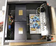
take another good look at the picture you posted.
The case of the Memisis is made up of steel plates, welded together (and not pretty).
Same goes for the 4 edges the top cover screws onto, welded at three locations to the case sides.
Welding steel plates, without significant warping, requires a minimum thickness, 2-3mm takes a full manicure to straighten the case out again.
Afair, base case sizes of the 9/9.2 are 48x48x25cm.
Specific weight of steel is 7.9 (metric)
A case in 4mm would go for ~30kg, 37.5kg for 5mm wall thickness.
The heatsink is a Fischer SK56, 300mm wide, 30 rib, 10mm base.
In the size used for the 9/9.2, it weighs in at about 3kg.
In the picture you posted, compare the heatsink base thickness with the one of the case, looks more like 5mm for the case.
Makes +40kg for the case+heatsink.
The anodised aluminum front plate does about 15mm, with the massive front handles added, think 10kg more.
Makes a half-time score of 50kg.
The covers for the transformers in the Memisis are also made of steel.
And as told way back in this thread, filled with resin.
Add to that some bolts and nipples, spares and change, and you're looking at less than 10kg for the transformers.
2KVA ? I don't think so.
(2 times 625VA toroidals do 10kg)
`
My goal is to have this amp to be able to provide a continious power of 350W in 8 Ohms, and as close to 700W in 4 ohms as possible .
700W/4R mandate 8 pairs of laterals per channel.
Fewer transistors , let say 4 pairs , might stand the output currents
but they wont handle the amount of power reliably if ever the amp
is pushed to its limits.
communication
I do about a dozen languages fluently, try me.
I wasn't joking, but seriously making an effort to explain you something.
(btw, all I did was copy 4 of your lines, and exchange 2 words. That was both amusing, imo, and I was trying to make you see something)
My usual way is attempting to make folks come up with answers themselves.
For a genuine certified school teacher, try AndrewT.
(sorry, Mr T, spank me
<= humor part)Goldmund made the power supply of the Memisis as a Limp Dick on purpose.
Rail voltage is supposed to collapse at high output, low impedance.
Lateral Mosfets can handle short circuit, they have a built-in safety mechanism.
What they, just like any other semi-conductor, can not handle is overheating.
That's when they Pop.
Going from 250 to 350W output translates to peak dissipation doubling (1.4 squared)
Thermal resistance (Rjc) of the 125W devices is 1.0C/W (125C divided by 125W)
Add 0.3C/W minimum for the insulator (Rcs), makes 1.3C/W
(compared to 1.6C/W minimum for the J50/K135. The bigger pairs are J55/K175 and J56/K176, btw)
Do the math yourself for your oversized heatsinks, there's is No way a passive heatsink will be able to compensate, in any size.
A way to hot rod a car is to exchange the entire drive-train.
Not just a bigger engine, wider wheels, and a transmission intercooler.
May drive fine in the city, but full throttle on the track will be OK for a minute, then goes the tranny.
(Mr Wahab beat me to it again. Ce sont toujours les Algeriens.
)
Last edited:
I am happy for Your skills in languages, wich I am sorry I have not.
But do You have Norwegian among the languages You master fluently, I will be impressed. OK?
I am very sorry, but I could actually see neither humour nor advices in Your postings.
Just some comments leaving nothing else than quwestionmarks of what You really wanted.
Anyway, I am glad we are in some more productive conversations now.
Even if My skills is not up to Yours in, for me, foreign languages.
As I stated in a previous posting, I found myself very embarrased.
I had it in my mind this was a 350W amp. But I was terrible wrong.
This is now going in to my calculations, and also the maximum output at 3 Ohms of 400W.
Ofcourse this alters the whole build quite a bit, and also all calculations of what I need to make theese specs happen.
Here it is:
400W in 3 Ohms equals 35V wich in turn equals 8,6 A.
This will now go in to my calculations for determining the size of the transformers.
Where I have heard it, I am not completely sure of, but there was told me that the transformer in the Mimesis 9.2 was at more than 2,5KVA.
I have learned that the truth was only 1000VA Boomer I would say.
Should I disregard all other losses this means I would have to cool off 600W.
I have no trouble seeing that this is not possible withoud aided cooling in some way.
Goldmund made it without, in some way.
Tandberg have a similar setup as I am about to make.
But the shere size and available area inside the amp should be a good guide.
There even could be fun to add some profiles inside the amp to aid this.
It is never funny to be totally off track when building devices as this amp.
That is by the way, tyhe reason I am here in this DIY-forum.
To get help with what I am about to build, and if some powers beyound our understanding would allow it, let me share the nowlegde I have.
Now I will go back to the calculator and determine what power and transformers I would like to put in here. I have for years now used a (we call it this in Norway) Thumbfinger rule, that I put in a transformer about three times the power of what I wamt out of my amplifiers. This has never, ever, gone wrong so far.
8,6 Amps point at a transformer of 946 VA, wich is nearly excactly what Goldmund have in their M-9.2 Well, I think I stick to my rule.
And add the fan, with a control system I have used for years and years already.
This system is adjustable to nearly any temperature between 100°C and 20°C.
The steepness of the speed of the fan is also widely adjustable, aswell as a "silentmode".
This silentmode is always overruled by a high temp "alarm". Should the temperature reach this point the fan automaticly will be set to full speed until the temperature is under this switchpoint. I have used this for a lot of PA-amplifiers I have built over the years, and I know for a fact that most of them are still in use. Never had a repair on other than those I have chrashed during severe testing.
Well back to this amp.
I think I still will add the two extra 625VA transformers. The railcollaps I might make happen anyway. Quite simple actually.
Also used this in my PA-amps. Simply a bulb from a car. In series with the rail, between two capasitor banks. When reaching around 8,3Amp, the rails will have collapsed with at least 12V. Also fine as fuse. When in need of larger collapse, I just put in a 24V bulb. Well, two in paralell, on each rail. Then the collapse reaches 24V.
The bulbs are all 100W H3 or similar.
Any comments so far?
Have in mind: This build is a 250W. My mistake to reffer it to be a 350W. OK?
Last edited:
700W/4R mandate 8 pairs of laterals per channel.
Fewer transistors , let say 4 pairs , might stand the output currents
but they wont handle the amount of power reliably if ever the amp
is pushed to its limits.
Left this as I by mistake had in my head that this was a 350W build.
I am now back to what Goldmund intended this amp to be: 250W in 8 Ohms, and 400W in 3 Ohms.
MUCH easier to achieve, I think.
Standard procedure for output stages is to have the heatsink take 50% of the temperature rise.
Goes both for class AB and class A.
For class A, because the idle die temperature mark should be at 85-87.5C Max, for long term reliability.
The heatsink should be at 50-55C Max, for safety.
From 25C ambient to 55C heatsink is a delta-C of 30.
From 55C heatsink to 85C die temperature is again 30C difference.
Another reason is economics, a 50/50 ratio for output devices and heatsink is more than often the cheapest solution.
So the class AB boys did/do the same.
(serious ones, not counting off-the-shelf consumer grade)
The SK56 heatsink of the Goldmund does about 0.30C/W for 200mm high in the book (from memory *)
Times 6 devices makes 1.8C/W
(The heatsink of the Memisis is attached to the case, with plastic stand-offs. So the largest part of the heatsink is actually not touching the case, but hanging in Free Air. Though the L-profile for the Mosfets is closing up the bottom opening completely, the way the heatsink is positioned might even save some extra thermal points, btw)
Theoretically lowest Rjs for a J50/K135 is 1.6C/W with the 0.30C/W TO3 mica insulator, in practice higher than that.
Rjs for the 125W devices should also be taken closer to 1.5C/W (instead of 1.3)
For class AB, Max dissipation is at 125C die temperature rise from 25C.
50% is 62.5C
62.5 divided by 1.5 makes 41.67W for each Mosfet. (60/1.5 +2.5/1.5 *)
Times 6 devices makes 250W max dissipation. (375/1.5 *)
Take rail voltage at 80Vdc, plus 10% for peaks, makes 88Vdc.
Suppose max dissipation occurs at an output voltage of 1/2 x Vrail.
Makes the Vds droop : 44V
Power loss : V squared divided by load impedance.
(44 x 44) /8 = 242W [(22x22)/2 *]
Implies that the Memisis is thermally optimised for an 8 Ohm load !
242W x 0.30C/W for the heatsink makes a delta-C of 72.6C
72.6C + 62.5C = 135.1C + 25C ambient makes 170.1C (minus a few points for 242W instead of 250, [8Wx1.5]/6=2C)
Max die temperature is 150C. (Goldmund just likes living on the edge, counts in rail droop)
The thumb rule of taking transformer VA 3 times the power in 8 Ohm is fine.
Second rule is Not taking VA substiantially higher than total Pd of the output devices.
Take max continuous efficiency of a transformer at 70%
For a 1000VA that implies a max continuous transformer output of 700W.
Tada : the output stage of the Memisis handles 750W max. (6 x 125W *)
(* check aids for me, i'm old school, head count saves pressing calculator buttons)
Last edited:
I had it in my mind this was a 350W amp. But I was terrible wrong.
Hmmm... Before I made a clone of the Mimesis, I knew all the currents and voltage in every nodes of the original schematic. I'm familiar with THD versus frequency, stability, distortion spectrum etc etc. I studied all the pdf of the parts used. Everything, not just the total power of the amp
The amp has been made with attention to details. So detailed that many objectivists wont "understand". You can say that the amp is in the vicinity of stability, to get the "required/selected" performance.
If you don't know what makes this amp so good, how can you upgrade it? What you will do is to design different amplifier of the same topology. And the chance seems very small as it is about the best of this topology imo.
Your favorite amp, the Tandberg. May be you think that it is good because of the power supply and the mosfet so you tried to bring those to the new topology of the Mimesis. But I guess the Tandberg is a current feedback amp. May be a symmetrical one (Sorry I don't search for more info because I don't own the mosfets used in the amp). So check out the SSA/TSSA/VSSA threads. It's my last resort for amplifier topology.
I think we can learn from building chip amps, that any small changes can change the performance of a system GREATLY. Changing voltage gain from 32dB to 35dB. Changing feedback resistor from Allen Bradley to Holco. Changing capacitor size and brand (ESR). Changing inductance/resistance between 2 capacitors in a CLC/CRC. Etc.
Nobody want to think about that when designing a discrete high power amp. But we can make a "rule of thumb" of what has the likelihood to make a good sound. Choice of supply caps brand has something to do with ESR. And smaller caps are "usually" sound better. If you have the time you can try listening to multiple 4700uF (as used by GM) and compare it to a multiple of 15000uF (same total capacitance). If you don't have time, then the rule of thumb is that multiple 4700uF may give better performance.
The GM even go further with the "crazy" mechanical grounding scheme, and extreme PCB trace design.
Seems as if we use the same calculator Vermeulen.
But believe me, my heatsink has a far better C/V.
I should guess the area is close to three times of the heatsink I have seen on pictures of the mimesis. On each side of the cabinet I have in mind, the heatsinks have a full area wich meassures 225X500mm. The base of the heatsink is approx 10mm in addition the fins are full 50mm long. With approx 30 fins each having a area of 225 cm² wich in turn ends up as near 7000 cm², that part of the cooling should be good.
In addition there will be forced cooling of the interior. wich adds up another area of 1100cm².
All in all around 6 kilogammes of aluminum on each side of the amp.
And unlike the mimesis: With forced cooling on demand.
Well, I think the cooling is well taken care of.
But do You see an inconsistent in what You are writing?
In a post earlier here You tell me that Goldmund on purpose construct the PSU to "kneal down" when high loads are present. In Your example over here You add another 10% to the rail voltage when calculating the power loss.
Wich one should I give attention to?
And another issue is this: When playing music over this amp, I will never experience the loads and losses described in your example. Actually I probably never will be producing an average power of 35-40Watt. Tops.
When looking at the losses in the transistors then I find a worst case scenario ending up with around 170W loss in the output transistors (40W in 8 Ohms equals 2,4A and 17V, resulting in 71V over the output transistors, giving around 170W)
Again to be cooled passively over near 7000cm² + 1000cm² with forced air.
Not counting in the airflow directly over the transistors bodies ang internal flanges.
As for the transformer size, we agree more than you seems to see.
The only reason for me to use two 625VA transformers for each channel, is because the price I pay for my transformers are only €57.- a piece. total €228,-
I have trouble finding two 1000VA transformer for this price.
The closest to 1000VA I have found was a 800VA transformer at ELFA at €245 alone. And that one was for industrial lighting (airport runway lighting)
Farnell have 1000VA toroids for around € 286.-
Still when I made the wrong calculations at the start, I save more than half the pice for my transformers. I apretiate such savings, and then have some more to spend on other things in the amp to do it as good as probably possible.
Included an upgrade from 3 pairs per channel to 6 pairs per channnel.
I am about to check my papers to determine the real C/W and real area of the heatsinks I am about to use. I guess I have even more to go on.
I feel you choose a rather inefficient transformer in your example.
The ones I use has internal losses (copper + Iron) at about 12 Watts.
Including regulation the efficiency is at 91%. Should give me around 1149VA for each channel. Well within all written and unwritten recomandations for a amp like this. well, maybe a bit in the upper end, but this only influences to a power reserve wich will lie there just in case I should need it.
And 12X125= 1500. Now the transformers got a tiny bit too little.
No worry, I like to have the output transistors having some headroom.
They simply live a little longer then.
Hmmm... Before I made a clone of the Mimesis, I knew all the currents and voltage in every nodes of the original schematic. I'm familiar with THD versus frequency, stability, distortion spectrum etc etc. I studied all the pdf of the parts used. Everything, not just the total power of the amp
The amp has been made with attention to details. So detailed that many objectivists wont "understand". You can say that the amp is in the vicinity of stability, to get the "required/selected" performance.
If you don't know what makes this amp so good, how can you upgrade it? What you will do is to design different amplifier of the same topology. And the chance seems very small as it is about the best of this topology imo.
Your favorite amp, the Tandberg. May be you think that it is good because of the power supply and the mosfet so you tried to bring those to the new topology of the Mimesis. But I guess the Tandberg is a current feedback amp. May be a symmetrical one (Sorry I don't search for more info because I don't own the mosfets used in the amp). So check out the SSA/TSSA/VSSA threads. It's my last resort for amplifier topology.
I think we can learn from building chip amps, that any small changes can change the performance of a system GREATLY. Changing voltage gain from 32dB to 35dB. Changing feedback resistor from Allen Bradley to Holco. Changing capacitor size and brand (ESR). Changing inductance/resistance between 2 capacitors in a CLC/CRC. Etc.
Nobody want to think about that when designing a discrete high power amp. But we can make a "rule of thumb" of what has the likelihood to make a good sound. Choice of supply caps brand has something to do with ESR. And smaller caps are "usually" sound better. If you have the time you can try listening to multiple 4700uF (as used by GM) and compare it to a multiple of 15000uF (same total capacitance). If you don't have time, then the rule of thumb is that multiple 4700uF may give better performance.
The GM even go further with the "crazy" mechanical grounding scheme, and extreme PCB trace design.
I think You, and many others misinteprets my signature.
The nick at first: I am one of relatively few who takes time to keep old TANDBERG-equipment going strong still.
The TANDBERGEREN nick is an acronym for: The one who salvage TANDBERG.
Then the signature: If you are getting to enjoy radio as some of us did back in the sixties, You would know that the TANDBERG receivers had a very good reception on all wawelengths. So when You want to relive that era, you sooner or later will end up using a TANDBERG radio.
The TPA3016 was NOT introduced by me in this thread.
But I agree that it is a very good amp. Noone can deny that.
As for capasitor bank and design of that, there is all too many qualified guesses out there. Yes, Low ESR is good, but more importand High ripple current. And not to forget the total impedance of the capasitor. All the way through the audio band at least. Often the first two go hand in hand, and have, when in contact with Audio signals, some influenve to what we hear.
When we have a good PSU, will two of theese parameters have less influence, but ripple current CAN give an idea of how fast the capasitor bank can deliver current to the amp, in absence of the transformers power.
When we look at the difference of the peak value of the output signal, compared to the rail voltage, we will find that the transformer is more involved in delivering the current the amplifier demands than some curves I have seen in here. But back to the capasitor bank I intended to build for this amp.
The mistake of believing that this build was a 350W amp, has lead me to do relatively many calculations regarding the PSU and components around it and the output transistors.
I was well aware of the other spesifications on this amp, and I am lucky enough to have listened to a pair of the originals for tgis project.
No need to bury my nose in any datasheets in other words.
And just because I have had the best instrument ever to validate the origin of this project, I was so incredible foolish to let the power of 350Watts fasten itself in my head. And just because ot thqt I had in mind a "combo" capasitorbank calculated. A total of 40 279uF per channel along with the 2X10.000uF on board, and another pair of large caps in front of it all.
Only to achieve the headroom I had in mind for a 350W amp.
Now, when I have the figures right, I will revise theese calculations and see if there is some other numbers landing on the table here.
Should rather written as my RL-motto is:
Learn at least one new thing every day.
I am living it out to the full.
- Home
- Amplifiers
- Solid State
- The Very Best Amplifier I Have Ever Heard!!!!