Great idea.
Great Anatoliy. I suggested it time ago but Andy tried it on output stage at the wrong operating point dismissing it. Is a great DHT, very linear in triode mode and I liked it when I tried it as preamp....
I don't think I agree with this. The CCS load will put in evidence the distortion of the valve itself without the impact of the load...
Yes but this is not representative for an output stage where the impact of the load is unavoidable! The horizontal load can never be a simulation of headphones or speakers and the valve curves do not behave all in the same way going towards the cut-off. If you measure the THD of a 2A3 with its typical 2.5K, or even 5K, load you will see...
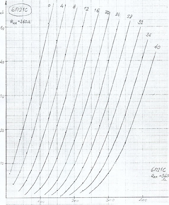
I did indeed try 6P21 at something like 45mA and 380v. Should have been more current and less voltage. I wasn't too thrilled, though. I suppose I should wheel them out again. In theory they're perfect for filament bias and a bit more output than the 4P1L, but in practice I don't know. They weren't very popular in Russia in the hi-fi community next to 4P1L and 6C4C. If they were a great sounding tube I suspect more people would have used them.
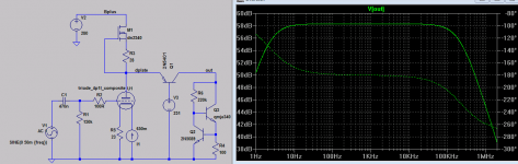
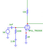
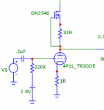
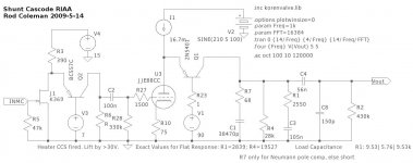
Running my input 4P1L with a CCS at 21mA does not seem to buy much gain. With an 11K resistor gain is about 7.5. With the simple DN2540 CCS gain is 8.8 Not much to write home about.
Perhaps I'm doing something wrong? See attached.
(note: I had to use 100R as Rset on the CCS to get 22mA, not 32R as shown)
Perhaps I'm doing something wrong? See attached.
(note: I had to use 100R as Rset on the CCS to get 22mA, not 32R as shown)
Attachments
I think that the 2A3 in general is not linear enough for this application. Regardless of the overall gain, at low output level distortion will always be a bit too much in you don't use feedback.
And if not for the 2A3, what do you think of a design where DAC (via high voltage opamp I/V circuit) drives the grid directly, eliminating the need for a DHT driver? No need for an interstage capacitor or transformer then, just one power DHT stage, whatever acceptable type it might be. I don't see the downside, but there should be a downside..
Yes but this is not representative for an output stage where the impact of the load is unavoidable! The horizontal load can never be a simulation of headphones or speakers and the valve curves do not behave all in the same way going towards the cut-off. If you measure the THD of a 2A3 with its typical 2.5K, or even 5K, load you will see...
I'm not disagreeing with any of this. I wasn't refering to the loadline in this case, I was pointing out the specific linearity of the valve and the impact of misaligned electrodes in old 45/46/2a3 or other DHTs.
My point was that the horizontal load line test is appropriate to characterise the distortion of any valve. As such, we can then use it to compare linearity of different valves with same method. There is most of a chapter in Morgan Jones' book dedicated to this subject in particular, in case you still think is not appropriate or valid test method
")
Ale
I am not saying it is not appropriate. I am just saying that it doesn't tell the full story. You might have perfectly aligned electrodes but overall linearity could not be first class because the spacing of the grid is not accurate enough. In a 2A3 it's a bit more complicated because you have 1 plate and 2 grids! A certain mutual conducatance depends on both electrodes spacing and grid spacing.
Last edited:
And if not for the 2A3, what do you think of a design where DAC (via high voltage opamp I/V circuit) drives the grid directly, eliminating the need for a DHT driver? No need for an interstage capacitor or transformer then, just one power DHT stage, whatever acceptable type it might be. I don't see the downside, but there should be a downside..
Triode strapped 4P1L because is at least just as linear (actually it is tipically better tha 2A3), has got more than double gain and all the ingredients for this application including low filament consumption and acceptable small size.
And if not for the 2A3, what do you think of a design where DAC (via high voltage opamp I/V circuit) drives the grid directly, eliminating the need for a DHT driver? No need for an interstage capacitor or transformer then, just one power DHT stage, whatever acceptable type it might be. I don't see the downside, but there should be a downside..
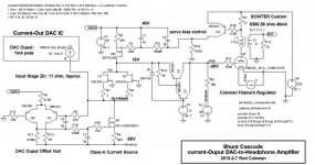
This is a splendid idea. And the HV opamp is not even needed...
Not only can the triode stage be eliminated, but the whole of the conversion from 1mA peak of DAC output can be dc coupled to the grid of the output DHT.
The circuit is, of course, shunt cascode. In this case, we use high-gm JFETs in common-gate mode, to present a low input impedance to the DAC.
The lovely 2SK369/LSK369, for instance, has a gm of about 45mA/V even for the Green grade, if run near IDSS. With 2 in parallel, we can get the dynamic input impedance down to about 11 ohms.
Shunt cascode does the rest of the work. The JFET drain voltage is fixed at 15V or so, and a nulling circuit balances the combined IDSS with a class-A current source, to maintain zero volts at the DAC ouput. (This can easily be changed to any value of offset, if you have a TDAxxx DAC).
The best is yet to come: this circuit can deliver dc-coupled output to the 4P1L grid of 18V peak (from 1mA peak input).
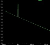
The FFT is of this grid voltage shows no sign of any distortion - because there is no reason for any: the JFET gm varies less over the 1mA swing than any triode, and the drain current varies very gently with drain voltage.
The attached FFT is shown for 35V peak-to-peak grid voltage!
The output is just Idac x R6, so you can set the gain lower, if you like.
Attachments
Last edited:
Running my input 4P1L with a CCS at 21mA does not seem to buy much gain. With an 11K resistor gain is about 7.5. With the simple DN2540 CCS gain is 8.8 Not much to write home about.
Perhaps I'm doing something wrong? See attached.
(note: I had to use 100R as Rset on the CCS to get 22mA, not 32R as shown)
You're not doing anything wrong - it just highlights the difficulties with conventional design.
The 4P1L has reasonable gm (maybe 6mA/V), but the Ra is so low that the anode current (the signal part) is wasted in it.
A gain of about 9 is the most you can expect, unless you shunt-cascode it - where the gain can be 50, 70, or even more.
One stage that gives you a gain of 794 (58dB). One cannot deny that in the "shunt cascode" the bjt DOES amplify the signal. Whether this is desirable or not is a subject for another discussion.
With a current source load, the gain is somewhat uncontrollable (just the same as with a bog-standard common-emitter amp with CCS load). This circuit would have to be used in a closed-loop amplifier.
Nonetheless, you can build a shunt-cascode amplifier with a (say) E180F (6688?), and use its gm of 21mA/V and a 30K resistor, and get almost the same gain with low distortion (dc servo needed though).
In all cases, the transfer function is:
Vout/Vin = gm x Rout [gm = triode gm, Rout = load]
In any properly implemented design, the BJT does not figure in the output - since the miniscule voltage and current errors it introduces are negligible.
you can calculate, or SPICE into the small hours, and you can build and measure, and you will find that this relationship is always true for any triode.
What's happening is that the problem Pano found (Ra reducing gain to only 8.8) is being solved by the BJT.
The BJT does not amplify the signal - it simply isolates the signal from the Ra of the triode. This isolation allows the load resistor (eg 6.8K) to develop high voltage without being molested by the triode Ra (eg ~1.5K for 4P1L).
So for a 4P1L, we can get a gain of -
6mA/V x 6.8K (= 40.8) ..............for shunt cascode
instead of the -
6mA/V x 1.5K (=9)....................for CCS load
I'm not disagreeing with any of this. I wasn't refering to the loadline in this case, I was pointing out the specific linearity of the valve and the impact of misaligned electrodes in old 45/46/2a3 or other DHTs.
My point was that the horizontal load line test is appropriate to characterise the distortion of any valve. As such, we can then use it to compare linearity of different valves with same method. There is most of a chapter in Morgan Jones' book dedicated to this subject in particular, in case you still think is not appropriate or valid test method
Ale
This is why I refuse to resort to the PX4 or the 307A, the odds of getting a good pair of these are very low. Odds are you get something some didn't want.
This is a splendid idea. And the HV opamp is not even needed...
Not only can the triode stage be eliminated, but the whole of the conversion from 1mA peak of DAC output can be dc coupled to the grid of the output DHT.
The circuit is, of course, shunt cascode. In this case, we use high-gm JFETs in common-gate mode, to present a low input impedance to the DAC.
The lovely 2SK369/LSK369, for instance, has a gm of about 45mA/V even for the Green grade, if run near IDSS. With 2 in parallel, we can get the dynamic input impedance down to about 11 ohms.
Shunt cascode does the rest of the work. The JFET drain voltage is fixed at 15V or so, and a nulling circuit balances the combined IDSS with a class-A current source, to maintain zero volts at the DAC ouput. (This can easily be changed to any value of offset, if you have a TDAxxx DAC).
The best is yet to come: this circuit can deliver dc-coupled output to the 4P1L grid of 18V peak (from 1mA peak input).
The FFT is of this grid voltage shows no sign of any distortion - because there is no reason for any: the JFET gm varies less over the 1mA swing than any triode, and the drain current varies very gently with drain voltage.
The attached FFT is shown for 35V peak-to-peak grid voltage!
The output is just Idac x R6, so you can set the gain lower, if you like.
Its common for head-phone amps to be integrated to the DAC, I think your approach here make the most sense of anything we have discussed. Lets face it the DAC is part of the amplification Iko is so worried about and if we are going to shunt cascode might as well start at the beginning. I know this is not good for analog guys, but if you have the bucks and space for analog you probably aren't a headphone guy anyway.
So I think this is the right approach, and I am glad you are showing current output, could use this with a good multibit DAC. I am all in on this, but it needs good filtering and of course a well layed out PCB to deal with the HF nasties of digital. The OPT helps but we need to prevent any HF funny business.
- Home
- Amplifiers
- Tubes / Valves
- The all DHT SET Headphone Amp