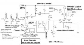
Serving suggestion for 4P1L - 2A3 dc coupled.
to keep Anatoliy happy, the 2A3 anode current servos the operating current of the shunt cascode, to give dc-stabilised operating point.
2A3 needs -100V bias supply (10mA), but this does give a startup voltage of -100V, to be kind to the 2A3.
Darlington connected PNP shown. NXP Semiconductors PBHV9040Z assumed for main PNP. others are -T package (SOT23) - so yes, PCB needed for correct layout.
To keep the 400mV (pk) sensitivity, the gain of the shunt cascode is increased to 62, to allow for the low mu of the 2A3. It's the beauty of shunt cascode - you can set the gain independent of the stage's triode current.
Attachments
I'm interested in the 4p1l-4p1l amp. The tubes are much cheaper than 2A3, and some of us don't really need more than .5 w.
I second that...
There is also two 71A lurking in my drawers...
")
although I'm sure a basic schematic from this thread could be adapted to use other output tubes, as different transformers suiting different headphone impedances could be employed (has been said before).
The thread is most interesting, almost a perfect match with what I have in mind. There is one unusual option not considered yet (unless I missed it). Sorry if it crosses some unseen lines in the sand or is plain silly.
If the DAC is made an integral part of this design, and its I/V conversion circuit (with HV OPAMP) set to swing the required grid voltage precisely, the DHT part could be reduced to a single 2A3. Also the interstage capacitor could be eliminated.
What do you think?
If the DAC is made an integral part of this design, and its I/V conversion circuit (with HV OPAMP) set to swing the required grid voltage precisely, the DHT part could be reduced to a single 2A3. Also the interstage capacitor could be eliminated.
What do you think?
I'm interested in the 4p1l-4p1l amp. The tubes are much cheaper than 2A3, and some of us don't really need more than .5 w.
I second that...
There is also two 71A lurking in my drawers...
although I'm sure a basic schematic from this thread could be adapted to use other output tubes, as different transformers suiting different headphone impedances could be employed (has been said before).
If can drive Sennhs HD 600 me too.
jpak
Stixx
merlin el mago
I thought that's been covered. A classic two stage 4P1L->4P1L should be fine for most headphones, provided you use the right output transformer. The first stage can use a gyrator load like I showed earlier, or a choke load, or the primary winding of an interstage transformer if you have the financial motivation to buy a good one. The output stage is simple, a 4P1L and the output transformer. The operating points are easy to calculate once you decide which parts you want to use. If you want it DC coupled, that's doable too, as I've shown earlier in a schematic. I've left some details out, but it's easy enough to figure those out.
To improve on that, keeping it simple, one can use 2A3 or 6S4S in the output. Or, if you can find it, the 307A. That's what I'm planning to build 4P1L->307A, first gyrator load, AC coupled, output transformer, and then later try an interstage transformer.
To improve on that, keeping it simple, one can use 2A3 or 6S4S in the output. Or, if you can find it, the 307A. That's what I'm planning to build 4P1L->307A, first gyrator load, AC coupled, output transformer, and then later try an interstage transformer.
The thread is most interesting, almost a perfect match with what I have in mind. There is one unusual option not considered yet (unless I missed it). Sorry if it crosses some unseen lines in the sand or is plain silly.
If the DAC is made an integral part of this design, and its I/V conversion circuit (with HV OPAMP) set to swing the required grid voltage precisely, the DHT part could be reduced to a single 2A3. Also the interstage capacitor could be eliminated.
What do you think?
I think that the 2A3 in general is not linear enough for this application. Regardless of the overall gain, at low output level distortion will always be a bit too much in you don't use feedback. Maybe you can find some 2A3's that are better than average but this means you cannot buy just two of them or two of them without tight selection. More likely you will get a colored sound. Pleasant as you want but not truly High Fidelity. 4P1L is better.
The urge for a Pout of 1W or more is not reasonable if you cannot have more important characteristics...
I've seen such beautiful curves measured of them!
sexy things
sorry, couldn't resist it 2A3 are extremely linear! I've seen such beautiful curves measured of them!
I have measured average 0.5 % THD for 100 mW output rising to 0.8% at 1W.
There is some irreducible distortion. You need tight selection to get a really good tube.
Best tubes were 6C4C's! The worst was the old 2A3 single plate!!
Yes, but 2A3 are expensive.
a pair of 4P1L can perform as well and as good as an 2a3. More importantly they are very cheap and easy to match. You can go for a 4P1L to 4P1L PSE. Sounds really good, albeit not tested Rod's circuit (yet)
Ale it's necessary to have a tube tester to match the tubes?
I was going to mention a similar experience but since mine was related to 46 valves I stopped myself from making a similar observation. I tested nearly 30 different valves, some NOS and many with electrode misalignment which becomes evident when pushing the valve to swing 200Vpp. When I got a good sample, it provided an impressive 0.18%@200Vpp whereas many samples about 0.5%: 46 DHT driver final tests | Bartola Valves
I did some tests to compare 4P1L to 6C4C and 4P1L were as good as the 6C4Cs...
Ale
I did some tests to compare 4P1L to 6C4C and 4P1L were as good as the 6C4Cs...
Ale
Felipe, What you need to match valves is for same mu. This can be done with an oscillator (test signal 1kHz at 100mV rms) and a high impedance load (e.g. CCS set at the Ia required) and measuring the output voltage. Given the high impedance of the load, then you can approximate gain=mu=Vo/Vi=Vo/100mv.Ale it's necessary to have a tube tester to match the tubes?
Ale
I was going to mention a similar experience but since mine was related to 46 valves I stopped myself from making a similar observation. I tested nearly 30 different valves, some NOS and many with electrode misalignment which becomes evident when pushing the valve to swing 200Vpp. When I got a good sample, it provided an impressive 0.18%@200Vpp whereas many samples about 0.5%: 46 DHT driver final tests | Bartola Valves
I did some tests to compare 4P1L to 6C4C and 4P1L were as good as the 6C4Cs...
Ale
Yes but that is not representative for an output stage where you don't have such a high load. CCS + high load makes many devices look better than they really are....
Yes but that is not representative for an output stage where you don't have such a high load. CCS + high load makes many devices look better than they really are....
I don't think I agree with this. The CCS load will put in evidence the distortion of the valve itself without the impact of the load...
- Home
- Amplifiers
- Tubes / Valves
- The all DHT SET Headphone Amp