Maybe true for modular instrumentation amplifiers but this circuit will only be connected one way in one circuit. It has passed all the requirements so far so even if CMRR is low, there may be little to gain from increasing it with this particular implementation.
R7/R8 give the + input slightly extra gain. At a current gain of 18.54k at the Jfet sources, this calculates to a CMRR of 2.85db, which seems to agree with the simulation. R7/R8 need to be bootstrapped to the negative input or replaced with current sources.
I think in the first simulation since you bypassed the 1k resistor you caused major offset which saturated/clipped the output resulting in optimistic PSRR.
I was thinking of both, CCS and bootstraping when I started this lineamp, but do I need all that complication? I am preparing PCBs and after listening to it I will deside upon implementing some of those upgrades.
Thanks Kean I like how you prceive all that electronic staff, realy remarkable.
Damir
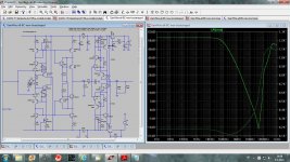
Only for the purposes of CMRR measurement do you need the CCS. R7/R8 act like a 11k resistor parallel to R9, so they are relatively benign except for noise conducted from the rails. However if your rails are well filtered with low impedance I don't think this is a problem. How much current is going through your BC5xx C-multipliers? BTW, 4.7k/470k for the C-multipliers seems pretty reasonable.
Only for the purposes of CMRR measurement do you need the CCS. R7/R8 act like a 11k resistor parallel to R9, so they are relatively benign except for noise conducted from the rails. However if your rails are well filtered with low impedance I don't think this is a problem. How much current is going through your BC5xx C-multipliers? BTW, 4.7k/470k for the C-multipliers seems pretty reasonable.
C-multiplier disipation is les then 80 mW(65mA) and it is 47k/470k.
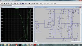
Attached is similar lineamp but with GNFB and sub ppm distortion. It will be easy to transform non GNFB one to the GNFB one, but I am not sure do I need that.
Attachments
The circuit without NFB is very inert. Potential reactive areas are the output CFP and Baxandall cascodes. They may need a small cap at their collectors or something else if they oscillate.
In any case, I've found inert circuits tend to have the most realistic imaging. The more positive and negative feedback paths, the more potential for adverse resonances and poor RFI tolerance.
It seems like a simple enough modification, maybe you can try it with an without feedback? You would have to bother with checking and compensating for stability though.
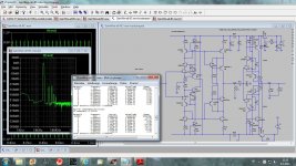
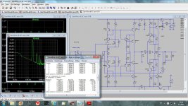
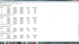
I`m working on something similar. What`s the nose level of input stage?
Noise is directly proportional to the R1 value, lover R1 lover noise, but higher distortion.
After the listening test I will decide what metters more, noise or distortion.
Attached two noise simulation.
dado
Attachments
I'll bet you could replace M1 and M2 with resistors without losing anything. Q17/18 will not improve PSRR, and bias loading here is relatively benign.
I suppose you mean CMRR not PSRR.
And you are right as usual, M1 and M2(CCS) and Q17/18 are not so important regarding CMRR, but without Q17/18 I've got three times higher distortion(it looks that main distortion source is output buffer now).
Now the best and quite simple(not as simple as Gaiwire with no CCS and no bootstrap) is to discard M1 and M2 CCS, but keep it in output buffer.
I think that this is now your circuit as much as mine Kean.
Damir
Attachments
Yes, I meant CMRR.
Dadod, here's something you can try for the output buffer. Put the zener in series with Q14/Q21 collectors. Then connect Q13/Q22 bases to Q14/Q21 collectors. This will get rid of the need for a bootstrap or CCS I think.
About current mirrors, I thought one of my recent posts was relevant:
http://www.diyaudio.com/forums/solid-state/192431-diyab-amp-honey-badger-19.html#post3312987
Yes, I meant CMRR.
Dadod, here's something you can try for the output buffer. Put the zener in series with Q14/Q21 collectors. Then connect Q13/Q22 bases to Q14/Q21 collectors. This will get rid of the need for a bootstrap or CCS I think.
About current mirrors, I thought one of my recent posts was relevant:
http://www.diyaudio.com/forums/solid-state/192431-diyab-amp-honey-badger-19.html#post3312987
Regarding current mirrors I am in accordance with you, look here http://www.diyaudio.com/forums/anal...conveyor-voltage-amplifier-8.html#post3300619. Mismatch in CM emitter resitor is the main source of the current conveyor distortion.
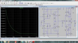
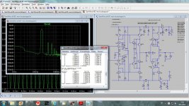
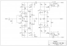
And now simulation with your proposed output buffer changes. THD20k was dobled but that is still so low and I think this is the best and simplest WireGain circuit diagram. That distortion is with 300 ohm load, so perfect for Sennheiser HD 580 Precision headphones(I have this one).
Thanks Damir
Attachments
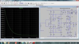
GainWire final version
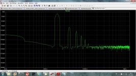
This should be final version of this line preamplifier. It is not preamp only, but could drive a headphones, like Sennhaiser(300ohm) and Grado(32ohm). Whith the Sennhaiser there should be no problem and distortion is in ppm level. Grado with its 32 ohm load is a bit tougher load but still distortion is quite low and very benign, look attached FFT. It was simulated at 2mW and Grado defined 98dB at 1mW.
dado
Attachments

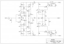
Collector of Q21 is broken.
Thanks, and LEDs instead zeners(D3, D4).
Attachments
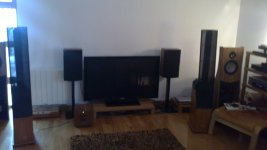
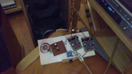
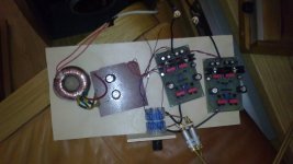
Finally I did first listening. Power supply was a temporary one very simple with 2x3300uF giving +-27 V.
I am really satisfied with the result even with this simple power supply. My intention is to design a shunt regulator for +-32V and I expect to get even better result with it.
First listening was done with simple circuit without bootstrap in the current conveyor part, that I am going to do next.
I have Aikido tube lineamp and I like GainWare more (could be because I designed it).
The source I used was Denon DVD 3910, lineamp GainWire, poweramp my AudioCube described in solid state thread, and loudspeakers were my design with a ribbon from Newform Research and 8” woofer from ScanSpeak.
Sorry for bad photographs, I've got a camera in my cell phone only.
dado
Attachments
Hi Dado,
Very happy to see your new little preamp ! Could you describe in a few words how is the sound and how it has improved ?
Best regards,
Nicola
Nicola, it was very short listening session and with just a simple power supply, but it was very promising. I will report again with proper power supply.
In a few words, great dynamic, clear voices and hights.
BR Damir
- Status
- This old topic is closed. If you want to reopen this topic, contact a moderator using the "Report Post" button.
- Home
- Source & Line
- Analog Line Level
- Current conveyor as a voltage amplifier