Are you starting to build the paradise ?
If those are your boards, your first try did indeed oscilate ?
No it's not mine, it's Beetle's
")
Hi Frans , sorry been calling you names. I thought that massive knob in the middle of the amp is the input resistor loading switch ie picture in the build guide. I don't have scope only a DMMs. How do i know if the psu is oscillating?. MY R3 after the ground being fixed still have some noise on it esp the channel with higher voltage on pin 6 of IC.
quan
. I thought that massive knob in the middle of the amp is the input resistor loading switch ie picture in the build guide. I don't have scope only a DMMs. How do i know if the psu is oscillating?. MY R3 after the ground being fixed still have some noise on it esp the channel with higher voltage on pin 6 of IC.quan
Hi Frans , sorry been calling you names
quan
Just do the counter measures, e.g. add the 4 capacitors, it does not harm anything. After that you will be sure it does not oscillate
even if it was not before (the resistors are not needed).And I have been called a lot of names, I’m sure the 'forum police' would have removed you post if you ware
(Using one of those). Anyway, no harm done, I just thought to have it corrected (the name issue ).
Last edited:
Hi Frans,
jep. builders manual says:
The way to fix this is quite easy, put two caps of 470pF parallel to C-B of
Q104 and Q204, and two caps of 2.7nF parallel to C-B of Q102 and Q202.
so its better to use 4n7 and 2n2 instead of the values in the manual?
and should this be any special type of capacitor?
as i understand, the capacitors do no harm, whatever the curcuit is oscillating or not.
thank you!
3) Added ce capacitors (as in the builders guide) but I had to use 4n7's and 2n2's to stop all oscillations.
jep. builders manual says:
The way to fix this is quite easy, put two caps of 470pF parallel to C-B of
Q104 and Q204, and two caps of 2.7nF parallel to C-B of Q102 and Q202.
so its better to use 4n7 and 2n2 instead of the values in the manual?
and should this be any special type of capacitor?
as i understand, the capacitors do no harm, whatever the curcuit is oscillating or not.
thank you!
Hi Frans,
jep. builders manual says:
The way to fix this is quite easy, put two caps of 470pF parallel to C-B of
Q104 and Q204, and two caps of 2.7nF parallel to C-B of Q102 and Q202.
so its better to use 4n7 and 2n2 instead of the values in the manual?
and should this be any special type of capacitor?
as i understand, the capacitors do no harm, whatever the curcuit is oscillating or not.
thank you!
Yes, that was the consensus from the simulations and some experiments, so I put it in.
These caps will limit the speed with which the current source will be able to react to line / load variations. When it is slowed down by this (and we are talking 2.5MHz), then the capacitors that are at the output voltages (C105 / C205, as well as the ceramic blocking caps in the amplifier) and the shunt regulator (which is not limited in its performance by these changes, as Frans pointed out) will have to work just a touch harder. No big deal.
As for the caps, a good foil cap will do (e.g. Wima MKS, FKP or similar).
Don't they slow down the CCS for bandwidth VS rejection performance to some extent?
Yes it does, it will limit the BW to just over 2Mhz (what is plenty). The shunt is doing the main work of course and that one will stay unaltered. My guess is that the CVS is influencing the CCS, for a future version I (may) have to alter the design a bit. Other measures (like the output capacitors) in the PSU and RIAA-decoupling will (for now) take care of that. As Hesener did say "No big deal"
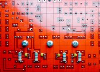
Here is a picture of my build. Suggestions for groundings? Currently still humming and more on the L channel ( measured 6V on pin6 of IC and test point of 6800uf capacitor).
Hi quan,
sorry I still don't understand which voltage at the test point you are talking about. Could you please measure the voltage right across the cap? That should be around 0.5...0.6V.
the 6V on pin 6 of the IC look like they probably will remain. This is an imbalance that would be worthwhile investigating further (might be related to your input stage transistors).
From your build, I think that looks fine. Could not really see the input loading resistor, is it soldered right to the input RCA? And, the blue wires that go to the middle, is this your star ground?
If so, you may want to put additional ground wires from the output RCA's to that star ground. Also, you may want to put additional metal plates ("bathtubs") around each paradise PCB, isolated from the chassis, but connected to the star ground at the input connector side.
hope that helps...
Hi Frans,
jep. builders manual says:
The way to fix this is quite easy, put two caps of 470pF parallel to C-B of
Q104 and Q204, and two caps of 2.7nF parallel to C-B of Q102 and Q202.
so its better to use 4n7 and 2n2 instead of the values in the manual?
and should this be any special type of capacitor?
as i understand, the capacitors do no harm, whatever the curcuit is oscillating or not.
thank you!
Using a 4n7 on the CVS is (I think (at this moment) ) the upper limit. I did use some small ceramics, foils would be better (as Hesener pointed out (but this is what was in my stock ).
Last edited:
Hi Alfred, the left channel -the test point is at the end of the line that run underneath the 6800uF cap which measured 5-6V. This is the same reading that i get on pin6 of IC. Do you think it is relate to the input transistors not matching up properly?. The input resistor is solder across the input RCA and the blue wire with 10R resistor goes to the ground post for tone arm. My PSU is on a separate box, do i still need to build a metal shield ?. I only have star ground on the psu box only.Hi quan,
sorry I still don't understand which voltage at the test point you are talking about. Could you please measure the voltage right across the cap? That should be around 0.5...0.6V.
the 6V on pin 6 of the IC look like they probably will remain. This is an imbalance that would be worthwhile investigating further (might be related to your input stage transistors).
From your build, I think that looks fine. Could not really see the input loading resistor, is it soldered right to the input RCA? And, the blue wires that go to the middle, is this your star ground?
If so, you may want to put additional ground wires from the output RCA's to that star ground. Also, you may want to put additional metal plates ("bathtubs") around each paradise PCB, isolated from the chassis, but connected to the star ground at the input connector side.
hope that helps...
quan
Hi Alfred, the left channel -the test point is at the end of the line that run underneath the 6800uF cap which measured 5-6V. This is the same reading that i get on pin6 of IC. Do you think it is relate to the input transistors not matching up properly?. The input resistor is solder across the input RCA and the blue wire with 10R resistor goes to the ground post for tone arm. My PSU is on a separate box, do i still need to build a metal shield ?. I only have star ground on the psu box only.
quan
Hi,
the test points all have a square layout and are labelled, except the test points right next to the emitter resistors of the current sources. The test point you are referring to might be round, in which case I think it is a "via" (connection between top and bottom layer of the PCB). Yes, that may be the output connection of the servo (== pin 6 of the opamp), this line is pretty long and winding....
The servo giving such a large voltage means it has to compensate a certain offset of the input stage. Remember the servo's impact is pretty weak, and deliberately so, so that voltage can reach several volts both ways. It should stay within +/-12 V though, in order to not leave the linear output range of that opamp. 5V is therefore OK. Best would be 0V, but that only happens with perfectly matched input stage, current mirrors, and output buffer with no offset.
While the mirrors's design is very clever so their impact on offset is negligible, the other two sources of offset may be the cause. On the output buffer, if the JFET Q99 has a high IDSS, the voltage on its gate will have to be negative so it operates at the current dictated by Q91+R15. So in order to have zero output offset, the voltage at its gate will have to be negative, so the servo must steer it that way. In my case, the voltage there is -1.5V (as documented in the annotated schematic in the assembly guide). Now, you could run the output buffer at higher current, by reducing R15, and thereby reducing this offset, but thats not needed for performance or sound.
On the input stage, if the current gains are not matched well enough between the NPNs and the PNPs, you may see that type of offset as well. In fact, it should be different for different values of input load resistance (you would probably have to look at values of 10K or higher to see something). It may also be that there is one transistor that exhibits base-collector leakage current, this is VERY rare but sometimes individual transistors excape the test program at manufacturing. You may want to try input resistors of 10K and 20K just to see if the offset changes. If it doesnt than just live with it, you should be fine. If it does, you may want to check if you can come up with another set of input stage transistors.
I would also suggest you remove that 10 Ohm resistor in the ground wire. The ground connection from the star ground to the ground connection on the PCB should be as low-ohmic as possible. Rather put the 10 Ohm in the ground connection of the power supply. In fact, the assembly guide has a detailed schematic from Frans on how to do the grounding on the power supply side which is very good. You want to have the TT ground, the phono preamp case ground and the PCB grounds as closely linked as possible. Please do connect the output RCAs to the same star ground. The power supply wiring on your picture is good.
hope that helps.....
Last edited:
Sorry, forgot one thing - the metal shields for the PCBs that should go in the phono preamp case help for two things:
- reduced cross-coupling between the channels. that doesnt change much, as the channel separation of the amplifier is way better than the cartridge
- hum and noise isolation to the case. this is a technique taken from test&measurement equipment, creating some kind of faraday shield right around the amplifier. it is important that the shield is isolated from everything, but grounded at the input star ground.
You could try with a couple blank PCBs under the amplifier PCBs, soldered with a little cable to the star ground, to see if it solves your problem. And, please put the star ground at the amplifier input, not the PSU box.
just my two cents....
Now, you could run the output buffer at higher current, by reducing R15, and thereby reducing this offset, but thats not needed for performance or sound.
This reminds me that at some stage, much earlier in this thread i had some problems with the choice of Q90/Q99. There simply wasn't sufficient voltage across Q99 and i had to find a suitable Q90. Not sure if this was just a freak occurrence, as apparently my build is ultraprone to those, or some advice towards the selection of the fets can also be incorporated in the build guide.
Eventually it turned out that both channels' output buffers were also running at very different currents and for the sake of obtaining better symmetry had to replace R15 with a multiturn pot.
Good points, I will do a couple more measurements and make suggestions to help with that.
Hello Alfred,
I second Benedetto's request ....
"Hello Alfred,
is it possible to you to put the link to your
fine, constantly actualized Builders Guide in your underline ?"
pleeeeeeaaaazzzzzz ;-)
It will make things much easier, you would even get less support questions...
JBdV
I second Benedetto's request ....
"Hello Alfred,
is it possible to you to put the link to your
fine, constantly actualized Builders Guide in your underline ?"
pleeeeeeaaaazzzzzz ;-)
It will make things much easier, you would even get less support questions...
JBdV
- Home
- Source & Line
- Analogue Source
- Paradise Builders