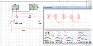
I used a single 100nf 500 volt AC capacitor.
Do you mean put two 47nf in parallel ?
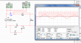
No, see the atached pictures.
Nigel_your is the single capacitor. Nigel_split is the split capacitor.
The error is because of the IRS27951 longer first impulse. At startup the middle of the split capacitor has voltage of half the primary supply voltage. So this cause less current transient at startup. It can solve the problem.
This all error is about the OC prot of the IRS27951. Its oversensitive
")
The datasheets recommends using FET with lower Rdson (it recommend that the calculated peak current times the Rdson should about 1V). The conduction lossws will be very small with this FET, so you can cahnge to IRS27952 if you want.
Attachments
This all error is about the OC prot of the IRS27951. Its oversensitive
The datasheets recommends using FET with lower Rdson (it recommend that the calculated peak current times the Rdson should about 1V). The conduction lossws will be very small with this FET, so you can cahnge to IRS27952 if you want.
I am already using 27952.
I tried the circuit with a 9 volt batteries and it didn't work.
The 9V is below the turn on treshold of the IRS2795x.
So even with IRS27952 the OC protection turns on?
The 9V is below the turn on treshold of the IRS2795x.
So even with IRS27952 the OC protection turns on?
I put 2 batteries in series to get 18 volts.
I also tried with my bench power supply and now it works.
So the problem must be to do with how I power the 27952 or the power up sequence.
I use a 6666R resistor dropping the 320VDC.
This should give 48mA which should be more than enough to power the 27952.
I thought I had connected 15 volts to the 27952 but I had connected it through a 1k resistor. So I tried with 20/25/30 volts but through a 1k resistor and it doesn't power up.
On power up with the 15 volts connected it is also getting some current from the 6666R
dropper resistor off 320VDC.
On power up with the 15 volts connected it is also getting some current from the 6666R
dropper resistor off 320VDC.
I have ordered some lower RDSon mosfets 0r22.
I have also ordered the 47nf capacitors to give that a try.
I think the circuit is just on the edge given the power supply bodge that got it running.
So hopefully the mosfets will cure it.
I agree, the circuit at start is on its overcurrent limit.
Using 2x47nF as I drawn on schematic will decrease the current transient at startup. Also a lower Rdson FET will have less voltage drop.
Also you can cahnge the 100nF to a single 47nF, then recalculate values for a higher frequency etc... This will decrease power output,and also peak current.
I few pages earler I sent you a Hungarian link. In that I used STP12NM50FP (Rdson<0,35Ohm). The resonant limited peak current is 4,98A. With IRS27951's 2V protection it starts with 50ms softstart time and 500kHz soft start frequency.
However I use some trick. The charge of primary capacitors is slown down by an NTC. I use a relatively low startup restior (100kOhm 2W) from 320V, and the supply capactior of IRS27951 is only 1uF. This way, the IRS27951 starts up when the capacaitors are halfway charged (about 200V), so at startup the current trasients are also less.
I tried the new mosfets and it sometimes powers up on its own.
I tried the 2 off 47nf trick but that wouldn't power up at all.
I will do what you said in regards using Cr as 47nF then alter timing resistors and see how I get on.
If you can also borrow and other inductance meter (not a multimeter type). And measure again the leakage and magnetizing inductance of your transformer.
Previously I said I have doubts about those values. Some inductance meters tend to give false values with ferrite transformers (but good values with iron powder cores etc...).
I started again from scratch tonight from measuring inductance to redoing the spread sheet input values.
Due to my poor eyesight I had not connected one of the secondaries to the output and this made my inductance readings wrong.
The inductances are now 620uH and 60uH.
I noticed with the spreadsheet altering it didn't change Rmin which seemed stuck at 68k.
So I downloaded your spreadsheet again and input all the correct values. It now gives much smaller values of resistors. This would mean my previous values put the 27951 into ZCS mode seriously.
However I tried to power it up again and it has gone back to the previous problem of needing a lab power supply attached to start up.
I am using a ct_ertek of 390pf.
What is the Ct ? that is 133pf
Is it telling me to use 133pf for Ct ?
Just out of interest I put in a low value resistor for Rmin and the circuit powers up every time.
I guess you are right that I am not getting a value right somewhere.
My inductance meter does measure down to 22uH with an inductor correctly so I don't think that is the problem.
Perhaps I am missing something in the spreadsheet ? perhaps I have misunderstood it somewhere ?
Last edited:
I am using a ct_ertek of 390pf.
What is the Ct ? that is 133pf
Is it telling me to use 133pf for Ct ?
Ct is the calculated timing capacitor.
The timing capacitor should be choose to set the proper dead-time.
Will in the FET datahseet values to the sheet "FETek", then you can choose it at cell B70.
I am sore there is some error, normal Ct values are between 330-470pF.
In Ct_ertek you should fill in the nearest (but larger) standard value.
I am currently using 390pf.
With 600uH and 60uH and 47nF.
I get:
Fr1 = 95000
Fmin = 28575
Fmax = 190000
Does this sound in the ballpark ?
There is some error with Fmin.
I get 56kHz. The 28kHz is unreal.
nigelwright7557;3329063 Just out of interest I put in a low value resistor for Rmin and the circuit powers up every time.[/QUOTE said:If I use 1k as Rmin the 27951 powers up every time.
This gives a frequency of 500,000Hz
Something is seriously wrong as it should run easily at frequencies below this.
- Status
- This old topic is closed. If you want to reopen this topic, contact a moderator using the "Report Post" button.
- Home
- Amplifiers
- Power Supplies
- IRS27951 / IRS27952