Hi all, I want to use a shunt regulator for the input and VAS of a class A amplifier, with an output that can be adjusted between 30V and 35V. Has anyone any views on two regulators from Jims Audio, one is a Kubota type and one termed "class A shunt regulator". They both have variable posative and negative outputs in the voltage range I require, with ample current.
Buying a kit would be an easier solution for me than trying to make my own PCB.
Thanks for your help
Alan
Buying a kit would be an easier solution for me than trying to make my own PCB.
Thanks for your help
Alan
I have a similar question about this shunt regulator PCB on ebay. It ships from Indonesia and is described as "overstock Shunt Regulator PCB design by Mr. Salas". Any comments would be really helpful...
I was interested in this one Low impedance 500mA class A shunt regulator kit ! | eBay
Alan
Alan
I bought two of those kits and they work ok. I didn't do extensive testing so I don't know much else.
Hi, I cannot find a circuit for the Kubota regulator, I presume it's a shunt type regulator, but I don't know for sure. Has anyone any details please? Here is a diagram of the second regulator I am interested in ( the class A shunt regulator ) does it look reasonable?
thanks for your help.
Alan
thanks for your help.
Alan
Attachments
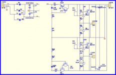
Hi, I cannot find a circuit for the Kubota regulator, I presume it's a shunt type regulator, but I don't know for sure. Has anyone any details please? Here is a diagram of the second regulator I am interested in ( the class A shunt regulator ) does it look reasonable?
thanks for your help.
Alan
I don't believe that is a shunt regulator. It looks like a regular series regulator to me.
Hi,
I've got a couple of Kubota regs that I would like to modify for better noise without sacrificing output impedance. Here's the diagram for one of them :
which is sold here :
HIGH SPEED LOW NOISE MOSFET POWER SUPPLY REGULATOR KIT! | eBay
and the other is the one from Jim's audio. It uses constant current diodes so it looks far simpler, like this below, but its really the same thing.

My main query is about inserting an RC filter after the voltage reference (D1 and D2 in top diagram) to filter noise into the error amplifier. Will this affect output impedance ? My brain says yes, but I don't trust it completely.
The other option is to increase Vref by using 2 LM329 in series instead of using gain. Is this design stable with unity gain ? Does it need a small cap to bypass the output feedback resistor for unity gain stability ?
For sure I know that the Vref's zener has a low impedance so the filter cap needs a film cap bypass to filter noise.
Are there any LT Spice sims for this circuit ?
Thanks,
Tom
I've got a couple of Kubota regs that I would like to modify for better noise without sacrificing output impedance. Here's the diagram for one of them :
An externally hosted image should be here but it was not working when we last tested it.
which is sold here :
HIGH SPEED LOW NOISE MOSFET POWER SUPPLY REGULATOR KIT! | eBay
and the other is the one from Jim's audio. It uses constant current diodes so it looks far simpler, like this below, but its really the same thing.
My main query is about inserting an RC filter after the voltage reference (D1 and D2 in top diagram) to filter noise into the error amplifier. Will this affect output impedance ? My brain says yes, but I don't trust it completely.
The other option is to increase Vref by using 2 LM329 in series instead of using gain. Is this design stable with unity gain ? Does it need a small cap to bypass the output feedback resistor for unity gain stability ?
For sure I know that the Vref's zener has a low impedance so the filter cap needs a film cap bypass to filter noise.
Are there any LT Spice sims for this circuit ?
Thanks,
Tom
Last edited:
Hi Dirk,
Thanks for the advice. I don't see any reason to use big electro's either. I thought about a film bypass for them but actually, a tant and a ceramic together would probably be far more effective.
I've been turning this design around in my head and actually I think the RC filter on the zener reference won't affect output impedance - it's not part of any of the output-feedback loop. Plus it'll give the psu a soft start.
I still can't figure out if it will be stable without gain - I think probably not. I've been looking at other series regs with unity gain and at least one uses a compensation cap - AMB's Sigma11 (C16 in his schematic).
Anyway, it's a beautifully simple design. To me, it shows some real lateral thinking and it's only real weakness is noise.
Cheers
Tom
I have a similar question about this shunt regulator PCB on ebay. It ships from Indonesia and is described as "overstock Shunt Regulator PCB design by Mr. Salas". Any comments would be really helpful...
Its not an authorized PCB and it looks like based on an old version. Please don't support the copycats.
Originally Posted by CZ101
I have a similar question about this shunt regulator PCB on ebay. It ships from Indonesia and is described as "overstock Shunt Regulator PCB design by Mr. Salas". Any comments would be really helpful...
Its not an authorized PCB and it looks like based on an old version. Please don't support the copycats.
Support the group buy ! Get quality for your money....
http://www.diyaudio.com/forums/group-buys/188974-gb-thread-salas-sslv1-1-bib-shunt-reg.html

- Status
- This old topic is closed. If you want to reopen this topic, contact a moderator using the "Report Post" button.
- Home
- Amplifiers
- Power Supplies
- Regulators from Jims Audio.