I don't follow.
I see % on the right hand vertical scale.
At the 0.1% level the harmonic for a 40Vpk signal (28.28Vac) should be 1/1000 or about 28mV.
The left scale shows values of voltage of 0.0003V (maybe 0.0002828), this is 0.3mV.
That to me seems to be a discrepancy factor of 100times.
Right scale is for THD only. Left scale is amplitude of individual harmonics. They<re not related, I just wanted the THD curve to be "close" to the others in the same graph.
When I look back at it, I notice that the scale on the right should be divided by 100... The amplitude scale on the left is correct as well as the THD curve itself, only the scale is wrong.
Last edited:
I will do these plots for other resistor values and other powers as time permits
Martin
Martin, if you're done with the simulation I go ordering parts also the 56R.
Perhaps this is also interresting to see, how coil is wound: http://www.diyaudio.com/forums/aksa/207772-fetzilla-build-documentation.html#post3051880
Also tell us the maximum bias setting when you finish.
Regards,
Rudy
I've made some more analysis varying the Rb and vBias and only vBias seems to alter the distortions behaviors. However as already mentionned, the recent simulations i've done demonstrate that a higher value of Rb seems to provide increased stability. In simulation it even permits to lower the miller comp cap without compromising the initial "advised" stability.
As an example, at 10KHZ, with Rb of 22 Ohms, the simulator struggles sometines to plot the oscilloscope trace as rigning appears on the positive side of the wave. Lowering Rb to 10 Ohms makes things worse. Increasing Rb to 56R or 100R erradicates that propblem.
Leaving Rb to 22 Ohms and decreasing Cdom also worsen the problem while increasing Cdom erradicates it as well.
Increasing Rb to 100 Ohms permits decreasing Cdom to 100pF (in place of the 180pF) without compromising stability. I can definitely conclude that there's some kind of relationship between those two. As I'm no engineer on that matter I can only report my observations and draw rough conclusions around it.
My plan is to open the real box and increase Rb to 100 Ohms, increase the bias and test it. One channel at a time. Then when my observations are donw, revalidate the behavior in simulator to eventually try to lower Cdom to 100 pF.
That will bring me exactly at the values advertized by Dr. Self in his base amplifiers.
Martin.
canonnica, do you mean this Rb? that is interesting, can you keep me updated of your finds I mean if you don't mind, I'm making this layout from Alex MM original design with just a few modifications same circuit just placing them with more space I always like the MKIII from Alex MM layout, but I don't have special equipments nor oscilloscope to check, well that is mister Carlos job I just like layout designs, but is good to know you are checking and find better ways that is good.
thank you
Regards
Juan
thank you
Regards
Juan
Attachments
MJ's trannies are hard to find here in dubai, please advice a recommended replacement (Jap's counterpart)? Thanks.
-please, upload all information is the PCB, that looks great. -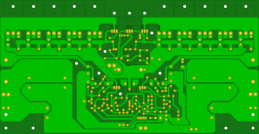
Do not alarm is just a test....
Regards
Juan
It is only a test.
and
Not yet complete.
this straight
I've made some more analysis varying the Rb and vBias and only vBias seems to alter the distortions behaviors. However as already mentionned, the recent simulations i've done demonstrate that a higher value of Rb seems to provide increased stability. In simulation it even permits to lower the miller comp cap without compromising the initial "advised" stability.
As an example, at 10KHZ, with Rb of 22 Ohms, the simulator struggles sometines to plot the oscilloscope trace as rigning appears on the positive side of the wave. Lowering Rb to 10 Ohms makes things worse. Increasing Rb to 56R or 100R erradicates that propblem.
Leaving Rb to 22 Ohms and decreasing Cdom also worsen the problem while increasing Cdom erradicates it as well.
Increasing Rb to 100 Ohms permits decreasing Cdom to 100pF (in place of the 180pF) without compromising stability. I can definitely conclude that there's some kind of relationship between those two. As I'm no engineer on that matter I can only report my observations and draw rough conclusions around it.
My plan is to open the real box and increase Rb to 100 Ohms, increase the bias and test it. One channel at a time. Then when my observations are donw, revalidate the behavior in simulator to eventually try to lower Cdom to 100 pF.
That will bring me exactly at the values advertized by Dr. Self in his base amplifiers.
Martin.
Just discovered that the thread has come alive again. The modifications contemplated by Cannonica were implemented in my Mk III when I observed instability after attempting to increase the quiescent bias. I found that an 56R base stopper completely eliminated the instability and allowed the bias to be increased to 57mv. per pair. This in turn substantially reduced measured THD. A further reduction was achieved by increasing the feedback ratio (and reducing closed loop gain). My amp has a gain of approximately 25 which is adequate for a system using a preamp but on the low side for those driving the amp with mp3 players. I'm also interested in reducing Cdom further (currently at 180pf) to improve slew rate. Look forward to hearing about the results of Cannonica's experiments.
mm*mm
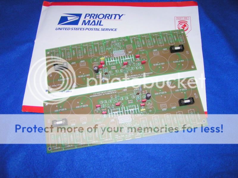
What size is the PCB?.
I wonder:
Where is this other design?
I find the pcb
Do not alarm is just a test....
Regards
Juan
What size is the PCB?.
I wonder:
Where is this other design?
I find the pcb
Attachments
Last edited:
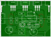
Juan have decided to produce his own board...his style
copied from the Dx Super A style.... we have worked hard to produce something that we think it is perfect.... and that one was the Super A pcboard.
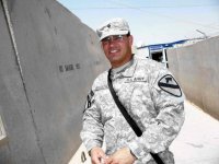
So, he is making, he sent me first layout and will have a lot of modifications, not approved for a while...soon he will publish and you may produce at home etching or to order pcboards from Juan... despite i do not think he will produce it to sell...he do not need...he is a veteran from Iraqui war, and receive payment as a military.... really, dear Juan, thanks God, do not need more money.... A hero from the Iraqui war.
But... we never know..... maybe he will be happy watching his work invading the whole world.... i do feel good when i know i have pcboards or my circuits in Siberia.... and this is very distant from my place.
The first board he made received a lot of complains from me...ahahahahaha!...now will start the longest novel ever made, to match our tastes..... he is from Central America...his genetics is Spanish and Maya....my genetics is Portuguese, Dutch and Italian mixed with African negro and brazilian native indians...what a mess!
Agreement will not be easy...the biggest friendly fight will now start.
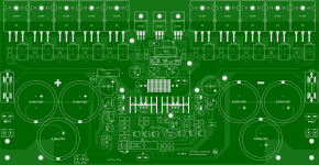
In my point of view, the Dx Super A amplifier layout is almost perfect..take a look on it...and you may see something on it applied to his new pcboard (he is making)
Super A, with bad pronunciation in a Brazilian way can be read as SUPERA, and this is Excel or overcome...and this is really the spirit applied on it.
regards,
Carlos
copied from the Dx Super A style.... we have worked hard to produce something that we think it is perfect.... and that one was the Super A pcboard.
So, he is making, he sent me first layout and will have a lot of modifications, not approved for a while...soon he will publish and you may produce at home etching or to order pcboards from Juan... despite i do not think he will produce it to sell...he do not need...he is a veteran from Iraqui war, and receive payment as a military.... really, dear Juan, thanks God, do not need more money.... A hero from the Iraqui war.
But... we never know..... maybe he will be happy watching his work invading the whole world.... i do feel good when i know i have pcboards or my circuits in Siberia.... and this is very distant from my place.
The first board he made received a lot of complains from me...ahahahahaha!...now will start the longest novel ever made, to match our tastes..... he is from Central America...his genetics is Spanish and Maya....my genetics is Portuguese, Dutch and Italian mixed with African negro and brazilian native indians...what a mess!
Agreement will not be easy...the biggest friendly fight will now start.
In my point of view, the Dx Super A amplifier layout is almost perfect..take a look on it...and you may see something on it applied to his new pcboard (he is making)
Super A, with bad pronunciation in a Brazilian way can be read as SUPERA, and this is Excel or overcome...and this is really the spirit applied on it.
regards,
Carlos
Attachments

Last edited:
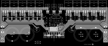
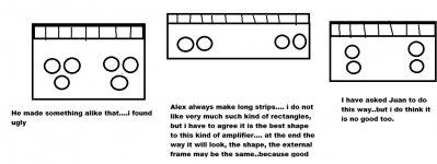
At the end, will be the way Alex mm did
The long strip i dislike, but it is the best shape to this kind of circuit that has a lot of power transistors.
here you see what is happening...the beginning of a big friendly battle of opinnions in between Jan and me.
He made the left image to make me happy as he know i do not like long strips..but really.... ti is the best solution despite i do not like.... both side options are worse.
regards,
Carlos
Attachments
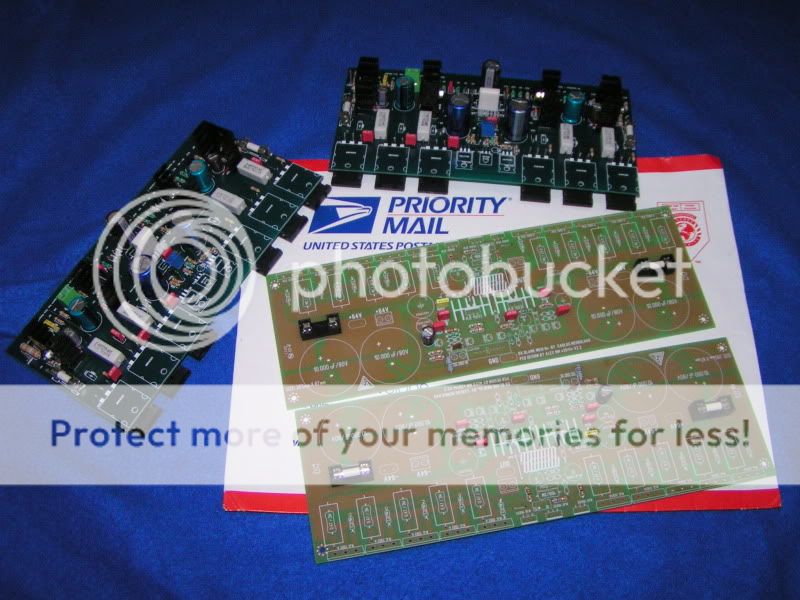
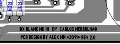
Guys.....! guys chill out!, is based on Alex MM original design my name is not on the layout........... check this out... . I know Alex MM is the original I do understand that is ok. Also is see a confusion of who made the board the original of course, so what is going on?
Regards
Juan
. I know Alex MM is the original I do understand that is ok. Also is see a confusion of who made the board the original of course, so what is going on? Regards
Juan
Attachments
Last edited:
- Status
- Not open for further replies.
- Home
- Amplifiers
- Solid State
- Dx Blame MKIII-Hx - Builder's thread