1.8A, 25V, 10mV DC offset, no temp compensation, no current limiting, bias is rock solid. Planning on turning up the bias until something breaks.
WOW! Is that .98 as in normally .59? Wow! What temp are the mosfets?
Russellc
WOW! Is that .98 as in normally .59? Wow! What temp are the mosfets?
Russellc
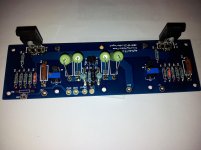
In the background on the meter it's DC offset @ 9.8mv. Across R11/12 I'm getting .85V. The fets are sandwiched between the cold plates, so it's bit difficult to get a temp reading; the water running through the plates is roughly 10C(50F), the fets do not heat the plates up whatsoever. I'm sure there's a formula somewhere that I could use to determine the temp....Jacco/AndrewT?? The plan is to slowly ramp up the bias, shooting for 1.5V across R11/12, roughly 3A. The 25W water cooled source resistors sure can handle it, we'll find out how robust these fets are...
Last edited:
In the background on the meter it's DC offset @ 9.8mv. Across R11/12 I'm getting .85V. The fets are sandwiched between the cold plates, so it's bit difficult to get a temp reading; the water running through the plates is roughly 10C(50F), the fets do not heat the plates up whatsoever. I'm sure there's a formula somewhere that I could use to determine the temp....Jacco/AndrewT?? The plan is to slowly ramp up the bias, shooting for 1.5V across R11/12, roughly 3A. The 25W water cooled source resistors sure can handle it, we'll find out how robust these fets are...
Well .85 is still incredible! Very cool. Those resistors are monsters...Carry on good sir!
Russellc
That's really nice. Is the 10C reached due to November temperatures or a water chiller of some sort?
You can calculate the junction temperature (very roughly) by using power dissipation of the FETs and surface temperature of the sink, adding about 0.4C/W for the interface resistance. Add the thermal resistance j-c and you should have a figure accurate to a few degrees.
You can calculate the junction temperature (very roughly) by using power dissipation of the FETs and surface temperature of the sink, adding about 0.4C/W for the interface resistance. Add the thermal resistance j-c and you should have a figure accurate to a few degrees.
The setup is messy. The cooling plate I'm using is: 3/8 In. Tubed Cold Plates - Cold Plates | MSCDirect.com. The fets are mounted between two plates, kapton tape, and thermal grease. The power supply consists of 1500VA trans, powered up by a variac, 68000uF - 4mH - 680000uF capacitors. The inductors are big 12ga. The F5 is stock, except that I removed the current limiter, and temp compensation circuitry, also the source resistors are 25W chassis mount. I suspect the thermistors would not be doing much in this setup. Once the bias is set, it doesn't wander. Today I had source resistor voltage up to 1.3V, and ran it at 28V rails.....no smoke yet. The cooling system consists of cold tap water running straight to it, and then to a drain....not eco friendly, but I don't listen for very long. The plan is to connect a chiller to it, and make a closed loop system. I'll put some more pics up in the next few days, for now....back to shovelling snow
-John
-John
F5 with one dead channel
Hi all, last night I fired up my F5 for the first time. I biased both channels nicely as described 0.6V over the .47R and output dc offset to less than 10mV on both channels.
I then went and connected source and speakers and the one channel is dead. no sound.
What can be wrong???? All transistors should be functional as the bias and dc offset voltage were achieved right? Why is there no signal coming through then? And I did check to see that the problem was not the source. Also the input impedance is correct thus no short there.
Any advice where to start fault finding will be much appreciated.
Thanks
W
Last edited:
well , picture of parts still in bags is almost equally useful

Thanks for the interest to help ZM!
If I pull the fets from the boards and test them to be ok I am going to look for the answer in the bottom of a bottle of whiskey.
Last edited:
W, where did you get your JFets from? I presume you didn't measure them before soldering, hmm? Asking because the world is flooded with fakes...Guess the culprits will most likely be the mosfets as they are static sensitive.
M
Hi Mike!!
I got them from B&M enterprises paid handsomely because I was afraid of the Chinese versions. I believe them to be good originals. But nooo...I did not measure them before installing :-o
I'm sure I must have damaged an output mosfet with static or something...all I can think.
I got them from B&M enterprises paid handsomely because I was afraid of the Chinese versions. I believe them to be good originals. But nooo...I did not measure them before installing :-o
I'm sure I must have damaged an output mosfet with static or something...all I can think.
Last edited:
you can't do much funnier thing on end of the week
but - do that with some company , and stay at 0,2L per head
NO NO...0.2L is not enough volume to achieve resonance!!!!
Last edited:
NO NO...0.2L is not enough volume to achieve resonance!!!!
Try barrel strength!
Russellc
- Home
- Amplifiers
- Pass Labs
- F5 power amplifier