Hi,
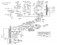
Anyone who know whether the shown CJ MV75 drawing is correct ? Please find the "new" updated drawing at :
https://picasaweb.google.com/103176...JohnsonMV75ModifiedToMV40#5799602912673127378
The Conrad Johnson equipment/amplifiers of any kind is very difficult to find in Europe. The possibility to build a clone seems to be one way to learn more about these great amplifiers. Any help with the CJ MV75 circuit would be highly appreciated.
regards.
It looks like most of the CJ amps I've worked on- later ones inserted a cathode follower between the input voltage amplifier and the phase splitter. It's basically the same circuit that Mullard and Eico used in the '50s and '60s, though Mullard used a pentode for the voltage amp and Eico used a 12AX7.
I contacted CJ via email and they sent me the requested schematic the next day. Not the one you're looking for, just saying you could try to do the same.
A very common circuit, however the power supply is not that common. And it has huge transformers. Those two things make the difference.
BTW, it is absolutely typical triode pre-driver -> long tail phase splitter -> UL push pull topology.
A very common circuit, however the power supply is not that common. And it has huge transformers. Those two things make the difference.
The schematic posted contains errors, and they appear to be deliberate.
Yes, thank you! Tell me where you have found the errors? Thats why I asked the forum!
I contacted CJ via email and they sent me the requested schematic the next day. Not the one you're looking for, just saying you could try to do the same.
Ok, good idea. I shall try to write to CJ.
rgds
Tell me where you have found the errors? Thats why I asked the forum!
The biasing of both the first and second stages is improper. I can't tell you what the "correct" version would be, since I don't know their intended operating points.
The biasing of both the first and second stages is improper. I can't tell you what the "correct" version would be, since I don't know their intended operating points.
Since you don't know their intended operating points, how could you then state that the biasing of the first and second stages is improper?
The biasing of both the first and second stages is improper. I can't tell you what the "correct" version would be, since I don't know their intended operating points.
The 90K9 looks like a misprint (or I didn't read it correctly). 90R9 would be more appropriate.
The 90K9 looks like a misprint (or I didn't read it correctly). 90R9 would be more appropriate.
Yes you'r right, this is a misprint...the well known MV75 circuit says 1K and 91R . It is 90R9 to gnd, as can be seen on the original schematic showed by gk7.
The "new" drawing is changed to the correct 90R9 . link:
https://picasaweb.google.com/103176...JohnsonMV75ModifiedToMV40#5799901426497056898
For more changes please write back
Last edited:
What is up with the power transformer secondary wiring for the E, F (opamp) supplies? Shouldn't there be a bridge rectifier there?
Either way, the secondary is short-circuit as shown.
Same drawing as in gk7 MV75 schematic E and F transformer secondary. D8 and D9 , as 1N4007 should be sufficiant, and the connection between the two rectifiers should not be there. C9 and C10 : 220uF/ 10V .....supply rails close to +- 8Vdc?
Drawing fault nr. 2 found
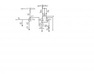
According to the MV75 drawing attached by gk7 the connection from 6CG7 pin 2 to between the resistors R23 and R24 is wrong on my "update drawing"!
In this case most of the signal is grounded through R24. The connection from 6CG7 pin 2 goes direct to 1M R28, and from R28 to 6CG7 pin 7. C15 0,47uF also from pin 7 to ground.
In this circuit we received approx. 200-210Vpp by change of 6CG7 plate resistors to 39K and changed to a better voltage balance adjustment.
The voltage pp is just about the same as the"self running" phase splitter with two 1M resistors and a transfer cap, but the distortion is approx. 3,334% at full power when the 6CG7 is depending on the voltage working point of ECC83/5751. At the "self running" phase-splitter the distortion stays around 1,1-1,2%.
The 6CG7 plate load was 100n/100K.
We have to work with the circuit and see if we can reduce distortion.
Yes it´s 90.9 Ohms not kOhms.
According to the MV75 drawing attached by gk7 the connection from 6CG7 pin 2 to between the resistors R23 and R24 is wrong on my "update drawing"!
In this case most of the signal is grounded through R24. The connection from 6CG7 pin 2 goes direct to 1M R28, and from R28 to 6CG7 pin 7. C15 0,47uF also from pin 7 to ground.
In this circuit we received approx. 200-210Vpp by change of 6CG7 plate resistors to 39K and changed to a better voltage balance adjustment.
The voltage pp is just about the same as the"self running" phase splitter with two 1M resistors and a transfer cap, but the distortion is approx. 3,334% at full power when the 6CG7 is depending on the voltage working point of ECC83/5751. At the "self running" phase-splitter the distortion stays around 1,1-1,2%.
The 6CG7 plate load was 100n/100K.
We have to work with the circuit and see if we can reduce distortion.
Attachments
Last edited:
CJ MV75A1 Schematic
Yes, +/- 8 volts. Early MV45's and 75's pulled this power from the filament winding. Later models had a small 12.6 volt center tapped transformer but only used half of the winding.
...supply rails close to +- 8Vdc?
Yes, +/- 8 volts. Early MV45's and 75's pulled this power from the filament winding. Later models had a small 12.6 volt center tapped transformer but only used half of the winding.
Yes, +/- 8 volts. Early MV45's and 75's pulled this power from the filament winding. Later models had a small 12.6 volt center tapped transformer but only used half of the winding.
Thanks, may I ask you one more question: By MV75, is it really with 590Vdc on the plates of 6550 , and B+ close to 630Vdc on the output centertag ?
Thanks, may I ask you one more question: By MV75, is it really with 590Vdc on the plates of 6550 , and B+ close to 630Vdc on the output centertag ?
I've never measured mine but the voltages are probably close. One of the Audiokarma guys measured 628V at the plates without the tubes installed so 590V with tubes sounds reasonable.
See post #47 of this tread;
project Conrad Johnson - power supply - part 1 - Page 4 - AudioKarma.org Home Audio Stereo Discussion Forums
Ron
Even with 590V we are pretty close to max. specs for the 6550 , and at post 47 you referred to, the DIY friends mentioned the KT90 for high voltages among other tubes....great CJ pictures in post 47.
Today we tried to make a spice model of the circuit mentioned here in #15. With approx. 162Vpp produced by the 6FQ7 we had less than 1% distortion on the plates. Nice.
Kim
Even with 590V we are pretty close to max. specs for the 6550
That seems to be normal on the older CJ's. All of mine (MV45a1, MV75, MV50 and MV55) run the outputs at or a bit beyond max specs.
Ron
- Status
- This old topic is closed. If you want to reopen this topic, contact a moderator using the "Report Post" button.
- Home
- Amplifiers
- Tubes / Valves
- Conrad Johnson MV75 "update circuit drawing"