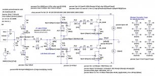
Here is a simulation of my latest circuit tweaks shown in the attached schematic. The purpose of these tweaks is to see how low I can get the 2nd harmonics and THD.
The primary changes are to allow one on the primary windings to freely float, the careful choice of the Rswip values to balance the AC currents through the source resistors, and the careful choice of C3 to null the 2nd harmonic at high frequencies.
The primary changes are to allow one on the primary windings to freely float, the careful choice of the Rswip values to balance the AC currents through the source resistors, and the careful choice of C3 to null the 2nd harmonic at high frequencies.
Attachments
The objective is to understand the role of the circuit parameters in determining the 2nd harmonic, not the configuration for best listening.
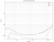
BTW: In the sweep, the sum of the harmonics greater than H3 is lower than H2.
BTW: In the sweep, the sum of the harmonics greater than H3 is lower than H2.
why trying all the time to have K2 below K3 and K>3 ?
your ears will start bleeding

Last edited:
The objective is to understand the role of the circuit parameters in determining the 2nd harmonic, not the configuration for best listening.
BTW: In the sweep, the sum of the harmonics greater than H3 is lower than H2.
agree for understanding
anyway - try to adjust to have K2 above K3 , then listen
btw - in sim , maybe is better to have one secondary flippin' in the breeze , but I think that better inter-coil coupling with both prim. connected , will give better results in vivo
Last edited:
With the winding floating, its AC voltage will be Vin*(Gain+1)/3 (ignoring all other circuit capacitances). If Gain=2, then the winding will float at the same AC voltage as the other primary winding.
agree for understanding
anyway - try to adjust to have K2 above K3 , then listen
btw - in sim , maybe is better to have one secondary flippin' in the breeze , but I think that better inter-coil coupling with both prim. connected , will give better results in vivo
I was thinking of better/tighter magnetic coupling between P and S
it is always better when you have P:S :S , than S:S
for my logic , better signal transfer will result in greater verity , even taking in account increased capacitive losses
I spent some time playing with MM and MC heads feeding various xformers , amongst others even repeaters (my lucida intervala ) , so those are my conclusions
anyway - check those sims with ears , and use whatever suits you more
it is always better when you have P:S
:S , than S:Sfor my logic , better signal transfer will result in greater verity , even taking in account increased capacitive losses
I spent some time playing with MM and MC heads feeding various xformers , amongst others even repeaters (my lucida intervala
) , so those are my conclusions anyway - check those sims with ears , and use whatever suits you more
Last edited:
Regarding sims (and nuclear arms treaties): Trust But Verify!
My objective is to understand how to get the best measured performance, and then add back harmonics in a controlled fashion. If I can null the H2 effects of the transformer interwinding capacitances, then I can controllably add H2 back with the Zen Pot.
My objective is to understand how to get the best measured performance, and then add back harmonics in a controlled fashion. If I can null the H2 effects of the transformer interwinding capacitances, then I can controllably add H2 back with the Zen Pot.
I was thinking of better/tighter magnetic coupling between P and S
it is always better when you have P:S
for my logic , better signal transfer will result in greater verity , even taking in account increased capacitive losses
I spent some time playing with MM and MC heads feeding various xformers , amongst others even repeaters (my lucida intervala
anyway - check those sims with ears , and use whatever suits you more
A P,S/S, P winding format, with an increase in wire size by one AWG diameter in the outer P, to help balance DCR and with the secondaries wound bifillar should eliminate all of these considerations. The two secondaries will be tightly coupled to each other, but this should be an improvement in distortion characteristics.
Bud
Bud
I am working with the Jensen JT-123-FTPCH transformer which is quadfillar. I am assuming (possibly incorrectly) that the windings are identical and have equal couplings to each other.
A P,S/S, P winding format, with an increase in wire size by one AWG diameter in the outer P, to help balance DCR and with the secondaries wound bifillar should eliminate all of these considerations. The two secondaries will be tightly coupled to each other, but this should be an improvement in distortion characteristics.
Bud
If two transformers are used in the way shown in the F6 Conceptual Schematic, there is still a problem. The AC voltages between the secondaries and the primaries are different. The top trafo has (Gain-1)*Vin AC voltage. The bottom trafo was -Vin AC voltage. If the Gain is chosen to be one, then the interwinding currents will cancel, otherwise they will not.
If the parasitic capacitance is a major issue as you suspect, then you could use two separate transformers for the two halves to prove the point either way, esp as you have two of the jensens already... Just my 2 cents ...
The sweet spot?
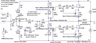
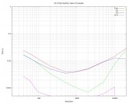
If the "spare" transformer winding is connected to a resistor divider generating (approx) Vout*(Gain-1)/Gain as shown in the schematic below, the interwinding parasitic currents are nulled.
I used a potentiometer to adjust the resistor divider ratio and generated the following harmonic distortion sweeps with slightly different adjustments of the Zen amount pot.
If you want to add more 2nd harmonic, use the Zen amount pot to increase it.
Attachments
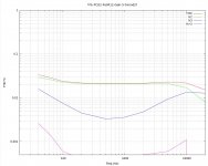
Zen, consider the 3.5k to 90k multiplication factor provided by the core, to any irregularity in the B Field transform from antenna to antenna up through 3.5 kHz. Then consider that it is physically impossible to wind quadfiller and keep all wires where they should lay. You can get a bifillar winding to couple perfectly, or very nearly so. You cannot say the same for four wires, wound into a narrow winding well, guided by either delicate fingers or uncontrollable mechanical traverse. The graphs shown will sound different, if for no other reason than where the differences are in the FR.
Contemplate the differences heard between two drivers, one with an uncorrected initial 4 ms response and one with a 4 ms response corrected with manic spots.
Contemplate the differences heard between two drivers, one with an uncorrected initial 4 ms response and one with a 4 ms response corrected with manic spots.
I can confirm by experiment today that the Zen Pot is a fine way to trim distortion level and spectra even in the case of feedback with Mufollowers like SIT2 (NFB) and J2 (FB)
the link again... http://www.diyaudio.com/forums/pass-labs/201655-lamp-simple-sit-amp-84.html#post2963216
the link again... http://www.diyaudio.com/forums/pass-labs/201655-lamp-simple-sit-amp-84.html#post2963216
I briefly experimented with that in the early days of my Teaser-6 build, but other parameters were too far from the "sweet spot" at the time to detect an improvement. I will experiment with it again.
You are overlooking another location for trimming the cancellation, which is
resistance across the secondary coils. Typical values would be on the order
of 200 ohms or more.
- Home
- Amplifiers
- Pass Labs
- F6 Amplifier