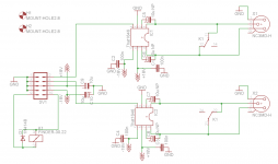
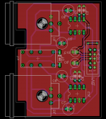
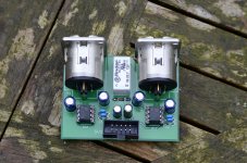
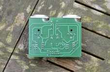
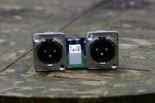
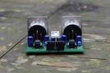
I made a pcb design for the That 1646 balanced line driver. I posted it on the dutch Zelfbouwaudio forum and Kostas alias TheShaman found it and contacted me if I had some spare pcb's.
I will post here some pictures, the schematic and gerber files so everybody can order the pcb's at for example Itead.
I will post here some pictures, the schematic and gerber files so everybody can order the pcb's at for example Itead.
Attachments

can folks who have used this chip, check this design?
I think the relay is wrong. the idea is that you can short one leg of the balanced output to gnd to make it drive unbal devices. however, it *looks* like its shorting both outputs of the line-driver together. this will cause the chip to overheat and also output a nice steady 0 volts")
or, am I missing something?
I think the relay is wrong. the idea is that you can short one leg of the balanced output to gnd to make it drive unbal devices. however, it *looks* like its shorting both outputs of the line-driver together. this will cause the chip to overheat and also output a nice steady 0 volts
or, am I missing something?
edit: I think I mis-interpreted the relay function.
it seems the relay will mute the output (the next stage will see the same value on both wires, so its a null input).
I was thinking this was a mode-setting relay, that converts the chip from bal into single-end drive mode (shorting the minus-output to gnd). but that's not what this relay is about.
it seems the relay will mute the output (the next stage will see the same value on both wires, so its a null input).
I was thinking this was a mode-setting relay, that converts the chip from bal into single-end drive mode (shorting the minus-output to gnd). but that's not what this relay is about.
the relay short across the output is a bit severe. Linux agrees.
Where are the output resistors to isolate trace and cable capacitances from the chip?
Use exactly matched 50r to 100r on each pair of outputs.
These need the same matching accuracy as the other resistances in the balanced feed.
Read Jung and Cordell about the need for these resistors.
Where are the output resistors to isolate trace and cable capacitances from the chip?
Use exactly matched 50r to 100r on each pair of outputs.
These need the same matching accuracy as the other resistances in the balanced feed.
Read Jung and Cordell about the need for these resistors.
the relay short across the output is a bit severe. Linux agrees.
Where are the output resistors to isolate trace and cable capacitances from the chip?
Use exactly matched 50r to 100r on each pair of outputs.
These need the same matching accuracy as the other resistances in the balanced feed.
Read Jung and Cordell about the need for these resistors.
Read the datasheet first........ No need for external resistors, outputs are shortproof
My review notes (Not intended as an attack):
You have a "pin 1 problem" in that the external cable screens connect via pin one to the internal single ended reference injecting noise and RFI, pin 1 should connect directly to the chassis and never to the internal reference (Which should be connected to chassis ground at a single point).
Where are the RFI measures? At present any RF picked up on the cable can get directly into the feedback pins, even ignoring the pin one issue. A common mode choke and some small NPO caps help here.
Where is the transient protection? Think P48 being present on a stage snake or similar, some diodes would be a good plan maybe?
Just what I see on a first look.
Regards, Dan.
My review notes (Not intended as an attack):
You have a "pin 1 problem" in that the external cable screens connect via pin one to the internal single ended reference injecting noise and RFI, pin 1 should connect directly to the chassis and never to the internal reference (Which should be connected to chassis ground at a single point).
That is not correct, pin1 is still a signal ground as with unbalanced connections and should be tied to 0v of the circuit. If I am incorrect, all proaudio mixing consoles are designed wrong.
Where are the RFI measures? At present any RF picked up on the cable can get directly into the feedback pins, even ignoring the pin one issue. A common mode choke and some small NPO caps help here.
You can take RFI measures as suggested in the datasheet, but they are not necessary. Have seen a lot of designs without this without problems. And those are not feedback pins btw, it is a common mode ofset reduction loop.
Where is the transient protection? Think P48 being present on a stage snake or similar, some diodes would be a good plan maybe?
If I designed this pcb for proaudio I might added it, but is for home audio use.
Just what I see on a first look.
Regards, Dan.
virtual all opamps have protection for current limiting.Read the datasheet first........ No need for external resistors, outputs are shortproof
That is not what I am talking about. Shorting the outputs while driving signal will cause the chip to enter temperature protection if it is fitted.
Fit the resistors. They are not for current limiting into faulty loading. They are there to improve stability and to properly couple the output to the cable or trace that follows.
I think you will find that most everything designed in the last ten years or so, has pin one bonded directly to chassis, see the AES48 standard for the reasoning.That is not correct, pin1 is still a signal ground as with unbalanced connections and should be tied to 0v of the circuit. If I am incorrect, all proaudio mixing consoles are designed wrong.
You can actually buy PCB mount XLRs that have a little spike so that when you do the screws up it punctures the paint to make a connection to chassis.
Basically, pin one may control the common mode voltage, but that does not mean that all the hash picked up in the screen should flow in your internal single ended reference where it can produce voltage differences due to the impedance of the traces.
This is not about voltage, it is about loop current and the screen current does NOT need to flow via your internal reference bus.
Both N. Muncy and T. Walderon have written extensively about this and while it took a while (And some kicking and screaming from the industry) most pro audio manufacturers have finally come on board.
See figure 12 here
Bonding Cable Shields at Both Ends to Reduce Noise
In fact read the whole thing.
You don't own a cellphone?You can take RFI measures as suggested in the datasheet, but they are not necessary. Have seen a lot of designs without this without problems. And those are not feedback pins btw, it is a common mode ofset reduction loop.
Leaving out RFI measures works until it doesn't, usually at the worst possible time, and they help with both susceptibility and emissions control, well worth the handful of extra parts in my view.
I also have a suspicion that much of the impossible to reproduce special cable mojo (to the extent it exists at all) is squarely down to audiophile kit designed without due care for immunity to RF...
Common mode reduction sure sounds like a feedback loop to me.
You never know where such a board will end up, it is worth designing the external interfaces to be very, very liberal in what they will accept up them.If I designed this pcb for proaudio I might added it, but is for home audio use.
I am afraid I personally do not subscribe to 'everything should be as simple as possible and then some".
Regards, Dan.
Some remarks:
The That 1646 needs no external output resistors, if so That would have mentioned it and they are designed to withstand output shortages:
OutSmarts Line Driver Clipping Behavior
P48 protection, very nice for pro audio gear but this a diy audio forum. BTW, you must be a complete idiot to plug in an output to a mic input with switched on P48..........
RFI protection, if you use your audio equipment at a sight with such high rfi levels becoming a problem, you should not be there in the first place. As long your interconnections do not pick up your mobile phone, it is fine.
The AES48 dogma, very nice but most of the time almost impossible to implement: a 48 in to 20 channel mixing console needs more than 212 wires to a star point ( 48 mic, 48 line, 48 insert, 20 output, maybe 48 direct outs).
AES48 does NOT advocate connecting the pin one connections to the star point, precisely because it is generally impossible to do it with low enough inductance never mind resistance.
Instead it advocates connecting pin one to the chassis as close as possible to each connector, which is entirely possible (And then connecting the chassis to the star point at a single location, so the screen currents do not flow in the audio reference but the common mode voltage is still controlled).
Actually doing it on a full up mixing console is really not a problem (Hint, Cadac had a lot to do with it, and they make some huge consoles).
Some of us run line AND mic on XLR (Actually very standard on some higher end kit) and hitting the wrong phantom switch is easily done, any output stage on XLR should be able to take it (and should ideally still put out signal).
With wide open kit like that, you better hope one of us with an amateur radio callsign never moves in next door! Even the UKs transmitter power limit (400W at feedpoint on most bands) will blow right through unprotected audio kit if you are within a few houses or so, and the US crowd get 1.5KW on most bands!
Regards, Dan
would ferrites be appropriate? or would they just be a waste of time/money?
If you use hundreds of feet of cable, yes ferrite beads.
AES48 does NOT advocate connecting the pin one connections to the star point, precisely because it is generally impossible to do it with low enough inductance never mind resistance.
Instead it advocates connecting pin one to the chassis as close as possible to each connector, which is entirely possible (And then connecting the chassis to the star point at a single location, so the screen currents do not flow in the audio reference but the common mode voltage is still controlled).
Actually doing it on a full up mixing console is really not a problem (Hint, Cadac had a lot to do with it, and they make some huge consoles).
Some of us run line AND mic on XLR (Actually very standard on some higher end kit) and hitting the wrong phantom switch is easily done, any output stage on XLR should be able to take it (and should ideally still put out signal).
With wide open kit like that, you better hope one of us with an amateur radio callsign never moves in next door! Even the UKs transmitter power limit (400W at feedpoint on most bands) will blow right through unprotected audio kit if you are within a few houses or so, and the US crowd get 1.5KW on most bands!
Regards, Dan
Well, 99,9999999% of the gear on this forum should be thrown in the dumpster directly...........
I have been working in the Pro Audio world for 30 years, never had a single problem with the "old" grounding method. The main problem is the EMC regulations, they are completely over exaggerated! To comply, your equipment have to withstand RF levels which will not occur in 99,99% in normal use. And I have never seen a burned signal cable........ Power cables yes, plenty
- Status
- This old topic is closed. If you want to reopen this topic, contact a moderator using the "Report Post" button.
- Home
- Source & Line
- Analog Line Level
- That 1646 balanced line driver PCB