So I am taking the reading correctly then?
You're right Pano, that's why I flagged this up, the datasheet says standard operating voltage is 3v, max 10. I've read that 5-6v is good.
Raising that 33k resistor is exactly what I thought I needed to do. Annoyingly I dont have any higher ohm resistors in my parts box and the shop is closed until tomorrow. Drat! I could just insert another resistor in series though right?
I'm trying to calculate the appropriate value resistor to use using the VIR equation but not succeeding. I can't figure out how to implement the equation for this problem. How do I calculate the required resistance to drop the voltage to say, 5v?
Last edited:
How to calculate...
the problem is the capsule may or may not behave as a pure resistance. What you could try.
A quick experimentation is probably the quickest way.
I'll think about calculating but it may not be ideal as the FET capsule is probably non linear in its current draw against voltage.
the problem is the capsule may or may not behave as a pure resistance. What you could try.
A quick experimentation is probably the quickest way.
I'll think about calculating but it may not be ideal as the FET capsule is probably non linear in its current draw against voltage.
A quick experimentation is probably the quickest way.
I kind of figured that actually. Shall I just experiment with inserting a resistor and measure what the voltage reads between the capsule terminals?
In this picture, A and B are both valid places to insert an additional resistor in series right? Pos A would mean putting it off the board, just inline in the lead the runs from the board to the capsule; B would be on the board, though trickier as the board is glued into it's casing now


There really isn't space on the board to get it right in there next to the 33, but I can snip the lead that runs from R4/R5 to point B and stick it in there. That'll make it easier to experiment with different values too.
I'm going to give it a shot now, will let you know how I get on.
[edit] I'm getting this advice from Reddit, not sure what to make of it:
Surely if a voltage regulator was necessary it would have been in there in the first place? As for the Zener, the original circuit featured a 12v zener, but Bill Ward told me to ditch it and raise that resistor to 33k.
I'm going to give it a shot now, will let you know how I get on.
[edit] I'm getting this advice from Reddit, not sure what to make of it:
[–]obsa
Don't use a resistor, use a voltage regulator. Especially because this is audio-related, you want your power as clean and stable as possible. Linear regulators are cheap and effective, but wasteful. Switching regulators are typically much more efficient under load but more expensive and often require an extra inductor.
[–]fatangaboo
Perhaps you can install a 5 volt zener diode in parallel with C1? This would prevent the microphone's voltage from exceeding 5 volts. Digi-Key will sell you the "1N5231" , a 5.1 volt, 100 mA zener diode, for twelve cents. Or 100 of them for $7.23. Jameco will sell you the "1N4733A" which is a 5.1 volt, 200 mA zener diode, for 6 cents (if you buy ten). Tayda Electronics is even cheaper [1] (IMAGE)
Surely if a voltage regulator was necessary it would have been in there in the first place? As for the Zener, the original circuit featured a 12v zener, but Bill Ward told me to ditch it and raise that resistor to 33k.
Last edited:
Don't think a voltage reg can be used here in this configuration.
Your new resistor has to go across a new cut in "row 11 B"
If super confident cut the 33K out at its body and tag a new value in soldering to the small wire ends that are left (or add wires to allow easy experiment of different values)
Your new resistor has to go across a new cut in "row 11 B"
If super confident cut the 33K out at its body and tag a new value in soldering to the small wire ends that are left (or add wires to allow easy experiment of different values)
I looked at that but isn't C4 connected there ?
I was thinking to do it like this, ie. the red line being the resistor. Is it no good there? But I see now that that wouldn't be quite where I thought it would be on the circuit diagram.
http://i560.photobucket.com/albums/...onverterLayoutforLinkwitzCircuitandBoard3.jpg
I'll get out my magnifying glass and try and slip it in with R3.
OK, so I inserted a 22k resistor in there. Managed to make them both fit nicely standing on end. The voltage across the capsule reads at 6.4v, and I inserted the ammeter into the circuit and it now reads around .46mA.
Now, that seems to be a reasonable voltage, though I'm worried of starving the capsule of current, the datasheet says the max current consumption is .5mA. Am I better off slightly decreasing the resistor value to supply more current, although with a higher voltage across the capsule, or do you think I've arrived at a good compromise?
Now, that seems to be a reasonable voltage, though I'm worried of starving the capsule of current, the datasheet says the max current consumption is .5mA. Am I better off slightly decreasing the resistor value to supply more current, although with a higher voltage across the capsule, or do you think I've arrived at a good compromise?
Could you just make a resistor voltage divider to hit your desired voltage? Keep the values a bit low so as not to limit current too much?
That's a new one on me, but I've just read up on voltage dividers a little and it sounds ideal. This diagram from Wikipedia seems to suggest I could simply run a resistor from say, 6B on my board, to ground.
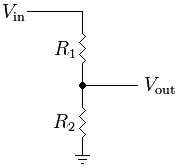

Is it as simple as that?
Well that sounds fairly straightforward then.
According to this voltage divider calculator (if I'm reading it properly) I could utitlise the 33k resistor, with an 18k to ground, to give me a Vout of 4.9v.
Yup, supply voltage is 48v.
According to this voltage divider calculator (if I'm reading it properly) I could utitlise the 33k resistor, with an 18k to ground, to give me a Vout of 4.9v.
Yup, supply voltage is 48v.
Sorry to double post here... But in an effort to understand what's going on here rather than just ask for instructions I wanted to ask:
- Is there any reason why I ought not to implement a voltage divider?
- What would be the potential ramifications of feeding the mic .46mA rather than .5mA?
- Is there any reason why I ought not to implement a voltage divider?
- What would be the potential ramifications of feeding the mic .46mA rather than .5mA?
Sorry to double post here... But in an effort to understand what's going on here rather than just ask for instructions I wanted to ask:
- Is there any reason why I ought not to implement a voltage divider?
- What would be the potential ramifications of feeding the mic .46mA rather than .5mA?
No problem... just that the answer isn't straightforward.
The voltage divider gives a know voltage according to the values chosen. So far so good. The problem is that as soon as you connect a load to it that voltage then alters. Your capsule is the load.
As to "feeding it current". Again its not so straightforward. If you take the capsule and apply say 3 volts, then it might draw (say) 0.4ma. At 10 volts it might draw 0.5ma and at 15 volts 0.53ma. Its an unknown and depends on the circuitry of the capsule. Another way of saying that is that the capsule draws whatever current it likes depending on the supply voltage. And thats normal. You will also see that the "current drawn" and "voltage across" the capsule aren't linear like they would be if the capsule were a resistor. That makes calculating exact values impossible without much more info such as graphs of the device characteristis.
So the capsule "draws" rather than you "feed".
The divider can still be used but again it becomes experimental in picking a value.
Great, thanks for that explanation Mooly. I'll experiment with some different values today, as well as with the divider, and see what kind of results I get.
If the max operating voltage of the capsule is 10v, and the max current consumption is .5mA, does that mean that those numbers are related? ie. at 10v it will draw a max of .5mA? Extrapolating from that, would it be fair to assume that at lower voltages, it will have a lower current draw?
Or is that an over-simplification?
If those values are from the data sheet then it would be interpreted as "max current draw" 0.5ma. That would apply to any sample of that device and none will draw over that. Most will be lower and there will be an average figure although that may not be quoted. It would be reasonable to assume that max current draw occurs at max permisable voltage. As you go lower in voltage though the current probably doesn't fall proportionally... this is the problem in calculating.
I'm sure you've seen all these,
Electret microphone - Wikipedia, the free encyclopedia
Recording and Measurement Microphones
I'm sure you've seen all these,
Electret microphone - Wikipedia, the free encyclopedia
Recording and Measurement Microphones
And another. This seems to evolve into your circuit,
Powering microphones
Powering microphones
I've seen and read through those first two but not the third, thanks for digging those up.
I've also been referring to this page How To Use An Electret Capsule With P48 Power: Balanced Signals and Phantom Powering For WM61A Microphone Capsules | Suite101.com
I'm trying all sorts of values here but can't seem to hit a sweet spot. I'm thinking it's best to maintain a .5mA supply since we don't have a graph of how the voltage/current correlates.
I'm wondering if maybe the 6v/.46mA will prove to be the best result.
Hi,
I have done the Linkwitz capsule mod and used his dual 9V battery powered OPA2134 Preamp. It works very well.
The main point to note is the modded capsule supply comes from the -9V rail.
I don't think your circuit is compatible with the modded capsule?
Some active D.I boxes use a SMPS from the +48V phantom to supply +/- rails of an opamp.
Just a thought.
Chris.
- Status
- This old topic is closed. If you want to reopen this topic, contact a moderator using the "Report Post" button.
- Home
- Source & Line
- Analogue Source
- Mic capsules distorting at low level in binaural dummy head. Why :(