It is interesting that even at the massive amount of capacitance you say you have it is evident in the display that the square wave top and bottoms is not flat lines but is lower on the left that on the right, the higher frequency (middle) plot is better but still reveals a sag on the left.
It could also be an indication of you choice of input capacitor filtering the low frequency, try increasing it if you want to see if this is the problem.
Thanks for the pictures Routhun
It could also be an indication of you choice of input capacitor filtering the low frequency, try increasing it if you want to see if this is the problem.
Thanks for the pictures Routhun
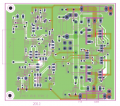
Thank you all who have contributed your time, ideas, expertise and investment. We have many PCB ideas in this thread including Alexmm, Drowranger and this draft of the type 2 which I post for your scrutiny(the clean version has minor mods). I am hoping Terry will also share his new layout with us. All the best.
Comments very much welcome")
Comments very much welcome
Attachments
Thank you all who have contributed your time, ideas, expertise and investment. We have many PCB ideas in this thread including Alexmm, Drowranger and this draft of the type 2 which I post for your scrutiny(the clean version has minor mods). I am hoping Terry will also share his new layout with us. All the best.
Comments very much welcome
All I can ask for the new revision is that you first check the hole size with components before sending to fab. It was way too tight last time... Had to drill some and force components.
Thanks
Do
Thanks Pinnocchio. As you can see the holes for the input capacitor have been widened to accomodate bigger devices. The holes of the MUR120 have also been widened.
Thanks!
Thank you Routhun. Yes this PCB is different, the power transistors, drivers, predrivers and bias transistor are all mounted under the board. They will first be mounted onto heat sink using a mounting document. Then the PCB shall be placed over them and soldered. Very compact. Measures 4 * 3.5. You could build a 7 channel amp with them
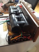
Folks - I think we have a psu..
It consist of a 500v trannie. Encapsulated. Looks nice.. I only got hold of 35v secondaries.
Measures with no load 49vdc.. (a bit high but lets se how it goes. )
8 pcs. hfa08tb60 diodes. I couple of ampohm 0.0022 uf over each secondary and a couple of 7.5 ohm power resistors after rectification. I have to make some measurements when the amp is playing. Maybe these are unnecessary?
Yes and a couple of 2.2kohm bleeders.
Attachments
Last edited:
Folks - I think we have a psu..
It consist of a 500v trannie. Encapsulated. Looks nice.. I only got hold of 35v secondaries.
Measures with no load 49vdc.. (a bit high but lets se how it goes. )
8 pcs. hfa08tb60 diodes. I couple of ampohm 0.0022 uf over each secondary and a couple of 7.5 ohm power resistors after rectification. I have to make some measurements when the amp is playing. Maybe these are unnecessary?
Yes and a couple of 2.2kohm bleeders.
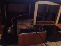
Almost there
. I wonder what you will hear with the first few notes Houston we have sound..
However with my main speakers (approx 97dB sensitive) the gain is just too much. I can barely touch the volume knob and it gets too loud.
I have to do something with that. Any suggestions?
Remenber I changed the input resistors some.. Not much but a bit..
And the input cap is 12uF.
Is it possible to bypass this BTW?
Soundwise - it got potential
Sorry about the really crappy pic..
I have not checked bias..
How to do this?
Attachments
Last edited:
 Thanks for the update Bambadoo. Cheers, you have first note
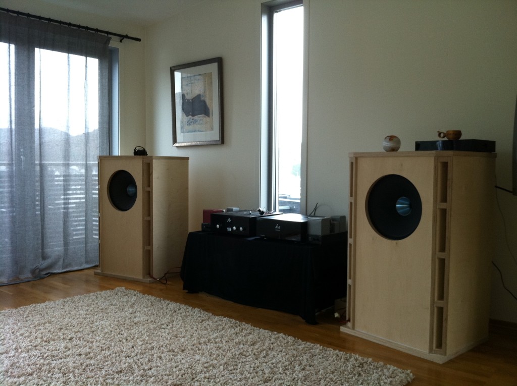
 Yes I almost fainted when i played Lee Ritenour as the first note. Holy crap - I felt the bass note right in my guts..
No the slight hum is there but I am not so concerned about that. It is a cable mess right now
And how hot should the heatsinks be? I can barely touch it.. I guess a bit above 50 degrees C?
I an hear hum (some hiss) for approx 3m away.
My preamp is an Audio Note l3 line.. With hi-B output transformers... Slightly (read very) modified.
I guess it has more or less the same data as audio note m8 (since I use e80cc-6463) tubes ... And a 33:1 OPT after that..
Under is the data for AN M8
Gain @ 1kHz 18dB
Input Sensitivity (for 1V output) 126mV
My setup looks more or less like this. The QuadIIs are gone...
Last edited:
- Home
- Amplifiers
- Solid State
- SYMEF amplifier