Hello
Can someone be so kind to send me some 300B schematics please...
I do not want to spend on tubes until I do not have a proven great sounding schematic.
Al do I have the amplifier enclosure, OP transformer, power transformer choke, PS capacitors etc.
Please help me if you can.
Thank you so much!
Greetings Gabor
How about an IT coupled design using the D3A as the driver tube? (Triode connected)
C3g in triode - 300B is on my plan.
some experimentals may be plate choke or IT. I did 1 pair choke of 130H 15mA and hope them are suitable for C3g.
I have IT 5k:5k, but it seems to be a little bit small impedance for C3g.
I suspect 5K:5K will work ok with the C3G which has only slightly higher rp than the D3A when triode connected, depends on the primary inductance and your target LF -3dB roll off frequency. (-1dB is 2X this)
130H chokes should work well with the C3G, hopefully the inter-winding and capacitance to core is reasonable .. I seem to have trouble getting beyond 60kHz in most choke coupled circuits.
This is going to sound odd, but the filament in the C3G seems to be quite fragile, a number of people have reported loosing hot tubes to minor shocks (like removal) so you might want to keep that in mind while debugging your design.
I suspect 5K:5K will work ok with the C3G which has only slightly higher rp than the D3A when triode connected, depends on the primary inductance and your target LF -3dB roll off frequency. (-1dB is 2X this)
my IT has nearly 20H on manual LCR meter at scale of 120Hz and max current is about 40mA. I think it is enough
")
This is going to sound odd, but the filament in the C3G seems to be quite fragile, a number of people have reported loosing hot tubes to minor shocks (like removal) so you might want to keep that in mind while debugging your design.
Could you say more clearly ?
Yes, the filaments can apparently break easily when hot if the tube is moved for any reason.
wow, maybe over heater Voltage is the cause ? . I will be cautious. Tks.
I think those German post tube are type of vibration resistance, also like Ba, Bh, Be tube ...
C3g in triode - 300B is on my plan.
Best sounding in pentode mode (on my plan) : 12GN7, 12HG7, EL802, EL183E
Attachments
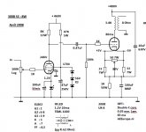
why do you use 10uf Cap connected K to B+ of 300B ?Best sounding in pentode mode (on my plan) : 12GN7, 12HG7, EL802, EL183E
Yves07 advises to do with this explication :
We always think the way "to go", eg the wire that goes from the anode of a power tube to the OPT, that common sense recommends short, but less often way back that "returns" from the cold point of OPT and crosses all power before joining the cathode of the power tube to close the loop!
Place a cap between the cold point of OPT and the cathode of the power tube avoids high frequency currents "go around" by the power supply.
Hence the expression "short way back."
Philippe
why do you use 10uf Cap connected K to B+ of 300B ?
It shunts some power supply ripple to the cathode to cancel the ripple on the output. The value of the cap from cathode to b+ should be [(C cathode to gnd)/mu]. I've found some fiddling with the final value necessary for complete ripple cancelation.
You'll find lots of this at tubecad.com...
It shunts some power supply ripple to the cathode to cancel the ripple on the output. The value of the cap from cathode to b+ should be [(C cathode to gnd)/mu]. I've found some fiddling with the final value necessary for complete ripple cancelation.
You'll find lots of this at tubecad.com...
seems that I have read this item before... does it reduce hum ?
If the amp has no hum, is it nesessary to get this Capacitor ?
I wonder if C 10uf here is also the shunt some audio signals from Ka to B+ ?
Last edited:
seems that I have read this item before... does it reduce hum ?
If the amp has no hum, is it nesessary to get this Capacitor ?
I wonder if C 10uf here is also the shunt some audio signals from Ka to B+ ?
Yes it reduces hum (b+ ripple).
You are right some audio signal will also go that way. Any alternating voltage, audio signal or noise signal will follow any path to a steady (non-alternating) node, either gnd or b+. In this case 1/10 of the audio signal will go to b+ since the cap to gnd is 10 times as large as the one to b+.
Isn't it Lynn Olson that has a good write up on signal paths and actually recommends bypassing the cathode to b+ and not gnd? In practice this only works when the b+ has extremely low ripple tho.
In practice this only works when the b+ has extremely low ripple tho.
Could you give me the formula of calculation on ripple of PSU ? what level does need this C bypass ?
Many thanks.
I meant in the case of bypassing the cathode to b+ only and not at all to gnd, then the b+ must have very little ripple, or the ripple will get amplified by the tube and you will have loads of hum.
To calculate the cap values see post 12. (C to b+ should be 1/mu of the C to gnd)
To calculate the cap values see post 12. (C to b+ should be 1/mu of the C to gnd)
Thank you kev!
Hopefully someone will come up with a good (sounding)working (proven) schematic.
I can go with other driver tubes to, only I mentioned the D3a or 6SN7 because I have them at hand.
OP transformer I have from Trancendar 3.5K, USA made (good quality).
I just wait for a good circuit and after I buy the 300B tubes.
Greetings Gabor
I meant in the case of bypassing the cathode to b+ only and not at all to gnd, then the b+ must have very little ripple, or the ripple will get amplified by the tube and you will have loads of hum.
To calculate the cap values see post 12. (C to b+ should be 1/mu of the C to gnd)
1/Mu+1... In practice the ratio is not that critical until you over couple ripple from the B+ supply into the cathode.. You can achieve quite significant levels of ripple reduction on the output.
Hi Gabor,
The D3A would be a great choice and since you have it on hand.. Choke load or IT couple it to a fixed bias or cathode biased 300B.. I'll post something over the next few days - I've used D3A with Lundahl 1635 IT to drive copper plate GM70 with very good results, something similar should work quite nicely for the 300B.
The D3A would be a great choice and since you have it on hand.. Choke load or IT couple it to a fixed bias or cathode biased 300B.. I'll post something over the next few days - I've used D3A with Lundahl 1635 IT to drive copper plate GM70 with very good results, something similar should work quite nicely for the 300B.
- Status
- This old topic is closed. If you want to reopen this topic, contact a moderator using the "Report Post" button.
- Home
- Amplifiers
- Tubes / Valves
- Recommended 300B SE Amplifier Designs