Big being relative of course.
I do not believe you have the capability to measure either for inductance to within 10%. It is neither easy nor obvious how to measure below half a nH.
jn
I think he's talking about distortion, where one had something like 0.000001% and the other had 0.000002%, a 100% difference.

Actually I was not thinking of inductance, but of element materials used. The inductance is too small for me to conceive of sonic differences. (Small resistances used.)
I am not inclined to believe it is a result of the materials used. I would be more inclined to think it is inductance. Not absolute value of inductance mind you, but how the field spreads out. When I need a low value power resistor in the 1 milliohm to 1 ohm range, I just make it such that there is no external magnetic field to speak of. My resistors run in the 50 to 100 picohenry range, but I cannot get reliable measurements below 250 pico, nature of the beast..
I've used both styles in circuits with sub nano response times. As well as BeO thin film cylindrical microwave resistors. None were low inductive (well, for what I needed), and that was because of the current centroid path.However, it is interesting since I checked since I saw no "non-inductive" comments on the Caddocks while Mills is listed as non-inductive. I take it you measured both? Mk-132s and Mills RA types.
Cheers John.
I did find one source of a nice resistor via NIST, but even that is not good enough.
Now I just make em to suit.
jn
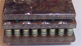
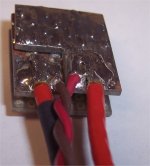
ps..pics attached. the first shows the array where all the resistors connect to the bottom plate, half to the top, half to the intermediate. Current goes in the top plate through half the resistors to the bottom, where it then goes back through the other half of the resistors. The current centroid for each path is through the other, so there is no net field. This resistor is made of 40 resistors. Big wire is current path external, twisted pair is for seeing the voltage on the resistor. The overall inductance is close to one resistor pair's inductance divided by 20. If you go larger, say 100 or 1000 resistors, the inductance goes down accordingly.
Attachments
Last edited:
I think he's talking about distortion, where one had something like 0.000001% and the other had 0.000002%, a 100% difference.
More like 1% vs .0001%!
Scott
As I wrote it is not an adaptive filter!
Ed, as usual, I don't know what you are refering to. If you think IIR filters are adaptive then you need a LOT of homework.
More like 1% vs .0001%!
Published? Never saw any of your articles with extraordinary data.
Ed, as usual, I don't know what you are refering to. If you think IIR filters are adaptive then you need a LOT of homework.
You mention I had problems with digital filter design... In the FT chat. The closest I mentioned was my problem with tilt on a feedback eliminator, which uses no DSP.
I did publish a Mills wire wound at very low power. I did not show the 1/2 power results as there were at that time no others to compare, it was only a small sample and lots of folks like them.
Now there are folks who seem to prefer or accept even order harmonics that parts like that make as they approach full power.
To me there is a difference between trying to design for the lowest added distortion and creating a musical experience. When we record music the amount of information lost is staggering. If you want to add bright colors to your room to make it more cheerful, that is fine.
Now there are folks who seem to prefer or accept even order harmonics that parts like that make as they approach full power.
As emitter ballast they don't even remotely approach full power.
I am not inclined to believe it is a result of the materials used. I would be more inclined to think it is inductance. Not absolute value of inductance mind you, but how the field spreads out. When I need a low value power resistor in the 1 milliohm to 1 ohm range, I just make it such that there is no external magnetic field to speak of. My resistors run in the 50 to 100 picohenry range, but I cannot get reliable measurements below 250 pico, nature of the beast..
I've used both styles in circuits with sub nano response times. As well as BeO thin film cylindrical microwave resistors. None were low inductive (well, for what I needed), and that was because of the current centroid path.
I did find one source of a nice resistor via NIST, but even that is not good enough.
Now I just make em to suit.
jn
Thanks for the information from your work John.
The resistances I use are higher ohmage. I believe it is more material as I have had similar problems terminating interconnect cables. Different types of solders required me to actually work with the external crossovers to achieve the same perceived "sound". This was some years ago. I originally discovered "the problem" in the lab doing some work.
Also interesting is that the IC that has 4.5 times the capacitance of mine (180pf vs 40pf) has a thinner sound than the ICs I normally use.
Cheers.
Last edited:
Also interesting is that the IC that has 4.5 times the capacitance of mine (180pf vs 40pf) has a thinner sound than the ICs I normally use.
Because of different diameters of solder used?
Try thicker solder, with rosin core. Rosin core does not thin the sound due to skin effect.
I did publish a Mills wire wound at very low power. I did not show the 1/2 power results as there were at that time no others to compare, it was only a small sample and lots of folks like them.
They list TC at 90ppm/C and I know of no other mechanism for nichrome wire to exhibit a voltage coefficient of resistance. 100C over ambient would involve an extraordinary application.
Because of different diameters of solder used?
Try thicker solder, with rosin core. Rosin core does not thin the sound due to skin effect.
Ever thought about becoming a comedian? I think you would have more success.
Cheers.
Last edited:
Ever thought about becoming a comedian? I think you would have more success.
Thanks, but I can't become everybody at once.
I knew you will like it!
Thanks, but I can't become everybody at once.
I knew you will like it!
Thanks. Have a great evening.
Positron, I feel your 'pain' in trying to get your opinions taken seriously. I take you seriously, however, and it has been a major key to my 'success' as an audio designer, among other things.
Many have heard differences in resistor types. WHY this is so, is beyond me, but it is pretty consistent.
The CTC Blowtorch uses four types of resistors, mainly. The major resistors are original Resista 1/2W devices, the servos 1/4W newer Resista devices. The power supply power resistors are Caddock, the 2W resistors are older Holco, and finally across the potentiometers, Vishay bulk metal resistors. EVERY resistor was considered and evaluated over the years. We selected what 'sounded' best to us at that location.
For the record, the Vendetta Research used 1/2W Resistas, except for EQ and input load resistors where I used 0.5%, 1/2 or 1/4W Holco (older construction). Newer construction Holco are not as good sounding. Resista does not make resistors anymore, so we NOW use DALE in both the JC-3, and the new Constellation phono preamps, two being designed at the moment, or Vishay bulk metal in critical locations.
Except for the color, kind of a 'brown', the Dales seem to work OK. Thanks Ed Simon for tipping us off about these devices. How's that for reality? '-)
Bob Crump found that the original Resista devices were the best overall, so we used them mostly. They used to cost us $0.05 in quantity, and $0.10 in small quantities, but that was 10 years ago or so.
At least one good reason is the method used for connecting the external lead element to the resistive element within the body during manufacture; there's always a chance of subtle non-linearities developing over time if it's not a 100% "perfect" connection ...Many have heard differences in resistor types. WHY this is so, is beyond me, but it is pretty consistent.
Frank
Interesting comment. I thought it was well-established (by experiment) that the ear is almost entirely insensitive to waveform shape, which is exactly what the filter-bank model of the ear would predict. Could someone put either me or Richard straight on this?
The insensitivity to waveform shape was afair mainly based on Ohm´s and Helmholtz´s experiments (although already back then there were other researchers with other conclusions) and was leading to the view of absolute phase deafness of our hearing sense.
But newer experiments showed that human ears are both, frequency analyzers and waveform shape analyzers.
It is for example required for ASA (auditory scene analysis) because the analysis of a complex soundfield would be quite difficult without considering the temporal relationship between frequency components.
Floyd Toole begs to differ. Consistent with his assertions, I was able to successfully identify under DBT conditions a stereophonic midrange all-pass using headphones, but not with loudspeakers (this was Hawksford's experiment, which John ran away from trying). If memory serves, Pano was also able to do this- neither of us are "golden ears," so I suspect many people could if they bothered to try. It was educational in that I now have a better idea of what the effect sounds like.
Consistent with his assertions, I was able to successfully identify under DBT conditions a stereophonic midrange all-pass using headphones, but not with loudspeakers (this was Hawksford's experiment, which John ran away from trying). If memory serves, Pano was also able to do this- neither of us are "golden ears," so I suspect many people could if they bothered to try. It was educational in that I now have a better idea of what the effect sounds like.- Status
- Not open for further replies.
- Home
- Member Areas
- The Lounge
- John Curl's Blowtorch preamplifier part II