The amp pcb is showing +42V on ch1 and -3.5V
amp#2 is showing -43V and +4.5
Could you elaborate
")
Stange to read those values with +12V/-12V PSU...
Wiring mismatch ?
For sure pics would be usefull as AudioSan says.
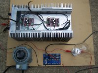
2x amps, 2x PSU in one chassis. The voltages are a bit high I guess from variac " juicing up" the power supply consist of Antek 4x15 400VA transformer. Basic CRC with 2x0.25R 5 W Dales. The power supply seems to be dead on. I used variac to bring it up to 115V slowly. The chain is: Variac, power strip with fuse buss, bulb, Toroidal wired both black wires together, both red together.
I then went to measure DC on the amplifier V+ and V- terminal and got the readings I reported. I check for voltage over the source resistors but had nothing, Z5 had 12V, and there was no offset at speakers maybe 5mv. I can post pics in a few minutes. like I said both pcb's were tested before. I'm afraid that handling might have blown a fet or two.
Thank you to all who help!
Steve
Here are pics:
I just returned home and tried to power it up again. This time the bulb starts to glow some @ 100V or so.
I tried checking for continuitee between all mosfets and ground, voltage terminals to ground, etc. Nothing that I could see.
I just returned home and tried to power it up again. This time the bulb starts to glow some @ 100V or so.
I tried checking for continuitee between all mosfets and ground, voltage terminals to ground, etc. Nothing that I could see.
Attachments

IIRC that was first edition "blue pcb's" These are later editions.
I think I solved it
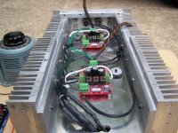
In the picture you can see there is 2 green wires running from PSU PCB, to CGROUND on Amp PCB. I connected a alligator clip between both speaker returns on just 1 strand of wire, and who would guess perfect voltages! I will connect both amp PSU PCB's to earth safety ground.
I did not think that I would need to tie both grounds together as its a 4 secondary toroid and its 2 seperate PSU. I guess thats what I get?
Is the 2 diode back to back, with 10R 10W resistor ground break ok for this system?
Steve
I think I solved it
In the picture you can see there is 2 green wires running from PSU PCB, to CGROUND on Amp PCB. I connected a alligator clip between both speaker returns on just 1 strand of wire, and who would guess perfect voltages! I will connect both amp PSU PCB's to earth safety ground.
I did not think that I would need to tie both grounds together as its a 4 secondary toroid and its 2 seperate PSU. I guess thats what I get?
Is the 2 diode back to back, with 10R 10W resistor ground break ok for this system?
Steve
IIRC that was first edition "blue pcb's" These are later editions.
I think I solved it
In the picture you can see there is 2 green wires running from PSU PCB, to CGROUND on Amp PCB. I connected a alligator clip between both speaker returns on just 1 strand of wire, and who would guess perfect voltages! I will connect both amp PSU PCB's to earth safety ground.
I did not think that I would need to tie both grounds together as its a 4 secondary toroid and its 2 seperate PSU. I guess thats what I get?
Is the 2 diode back to back, with 10R 10W resistor ground break ok for this system?
Steve
that was my next question
are the 2 green 0V wires conected correctly seams like they go to the wrong amp board.if they are mixed up(wich it seams to be) then you will have that crazy voltages.
Last edited:
I have a bag of thermistors somewhere, but where? Im not sure. I think I have a junk one pulled from a cpu in workshop I can grab now. I am going to run a green wire from the terminal on PSU PCB1 on and PCB 2 to the end of the junk thermister and tie it to chassis ground then.
Now to keep check on the mosfets and make sure the amp comes up to stable operation without anything overheating or smoking!
Steve
Now to keep check on the mosfets and make sure the amp comes up to stable operation without anything overheating or smoking!
Steve
moi prefer NTC solution , between system audio gnd and safety (chassis ) gnd
look in any generic FW PSU schmtc
i agree
i use one CL-60 pr ch to safety groundI have a bag of thermistors somewhere, but where? Im not sure. I think I have a junk one pulled from a cpu in workshop I can grab now. I am going to run a green wire from the terminal on PSU PCB1 on and PCB 2 to the end of the junk thermister and tie it to chassis ground then.
Now to keep check on the mosfets and make sure the amp comes up to stable operation without anything overheating or smoking!
Steve
but first. massure with diode tester the green wires, from PSU to amp. so you see if the corect PSU is conected to the corect amp.
I missed it, after planning, and setup, and check list.... Should have done more resting and walking away from the problem. Thank you guys for all the input, guys who are "still learning" are very thankful for the brother hood of PASS lurkers who help us out!
soldering and heatshrinking her now!
****** MAKING MUSIC NOW********
Sounds good crippled, I am trying to finish building my X-C+CCS-BOSOZ to really get it going.
Last edited:

Just a question for the gurus?
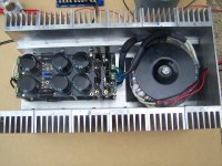
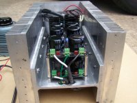
This is the first time that I have used larger oversized shoulder washers to bolt down the mosfets. I had seen many others do it and the rational is that it spreads the force over the MOSFET. I know Nelson uses them and that should be enough for me, but.....
Does the washer not act as a inefficient heat sink, and does that have any concerns for the MOSFET body. What temperature would be too much for a TO-247 body.
Thanks for the help,
Steve

- Home
- Amplifiers
- Pass Labs
- The Mini-A