Thanks for the replies guys!!!  It is so nice to see it work.
Like you all can see in the previous pictures the setup right now is far from ideal, but luckily it worked to test the lot") . Due to the bad wiring I was very suprised that there was no audible hum. Especially grounding is far from ideal right now. When I connect the oscilloscope to the speaker outlets, little hum arises because of a groundloop that is formed (the oscilloscope is grounded aswell). That is also why I have to measure very carefully and one channel at a time because both channels are not galvanic separated in the oscilloscope. Momentarily the only grounding point is at the chinch connectors from the pre amplifier. So at the end of the signalcables. I use an Accuphase E204 which I restored last year (yes I am very spoiled with that amplifier haha) as pre amplifier. The signalcables are very thin á la liquorice lace, long (almost 5 meters, so you can imagine how thin the shielding and thus grounding cables are) and cheap but it seems that this cable was usable for testing. It is almost unbelievable that there is still room for improvement while it sounds so good allready. There is a reasonable chance the amplifier will be even better because in the final setup the cables will be far more shorter and thicker.
. Due to the bad wiring I was very suprised that there was no audible hum. Especially grounding is far from ideal right now. When I connect the oscilloscope to the speaker outlets, little hum arises because of a groundloop that is formed (the oscilloscope is grounded aswell). That is also why I have to measure very carefully and one channel at a time because both channels are not galvanic separated in the oscilloscope. Momentarily the only grounding point is at the chinch connectors from the pre amplifier. So at the end of the signalcables. I use an Accuphase E204 which I restored last year (yes I am very spoiled with that amplifier haha) as pre amplifier. The signalcables are very thin á la liquorice lace, long (almost 5 meters, so you can imagine how thin the shielding and thus grounding cables are) and cheap but it seems that this cable was usable for testing. It is almost unbelievable that there is still room for improvement while it sounds so good allready. There is a reasonable chance the amplifier will be even better because in the final setup the cables will be far more shorter and thicker.
@David (Spurtle); you're welcome! I did not mentioned the missing track till I tested it. When I relooked to some of the pictures which I made at the start of the build I saw the track was really missing.
Dean (Neychi) has a blue version of Jim's boards. Dean showed me that his version has the track. There is a good chance that, when you have blue ones, this track is on your boards aswell.
When using both channels the heatsink gets hot, while when using one channel the heatsink does not seem to care. I would estimate about 60 degrees @ 400 mV bias when using both channels. From the other hand room temperature (@loft) is exceptionally high right now. Very nice wheater in Holland. The trannies at the intake of the tunnel are pretty cool (50 degrees or so), but at the outtake the trannies are hotter (would estimate 60 / 65 degrees) which AV werk mentioned earlier in this threat. So I think that it will exceed the 75 degrees when mounted in the cabinet, fans on less speed and higer bias. When that is the case, I think that I will change the thermostats to 85 degrees devices. But I have to measure temperature when mounted in the cabinet. Maybe I can borrow a nice temperature meter from University (they have very nice Fluke equipent over there ).
).
The dummy is capable to handle 2x 200 W @ 8 ohm, but when I turn the fan on 250 W per channel is not really a problem.
@Jozua: I realy hope temperature does not get out of control. Especially since I planned to mount the driver PCB's on top of the tunnel coolers. Between the tunnel coolers and PCB's I will mount a metal plate to protect the PCB's a bit from the heat. From the other hand this makes radiaton even harder. Altough I have to say, the tunnel coolers seem to radiate very little radiate heat when I sense the radiation heat from 4 cm distance. It seems that almost all the heat is transfered through the cooling tunnel by the fans.
@ A. wayne; there is a good chance Jim does not know. He has never mentioned it to me. I will sent him an email, maybe he can inform former customers this way also
@ David (AVwerk): Thanks for the tips!!! I am very gratefull for this tips. I did not really know how to test it next to the measurement I mentioned before. I will certainly post some scope pics while performing this tests! But that have to wait a few days till I have attached the leads a bit better and mounted the PCB's on top of the tunnel coolers. Everything is a bit loose connected right now, so attaching the probes and making pictures is a bit tricky.
That is by the way why I stopped using the amplifier right now (which was very hard, I wanted to make a little test, but had to play this record and that record... and before you know it is 3.00 p.m. hahaha). But I am afraid a cable will detach and make short circuit. Happend once when I was restoring an Luxman LV-103, be very careful when using cable clips, they can detach very easy
@ Dean, haha will do
@ DH biker: Will consider that! I still have to tink about a nice way of fancontrol and find a good bias vs. heat vs. noise ratio.
It is so nice to see it work. Like you all can see in the previous pictures the setup right now is far from ideal, but luckily it worked to test the lot
. Due to the bad wiring I was very suprised that there was no audible hum. Especially grounding is far from ideal right now. When I connect the oscilloscope to the speaker outlets, little hum arises because of a groundloop that is formed (the oscilloscope is grounded aswell). That is also why I have to measure very carefully and one channel at a time because both channels are not galvanic separated in the oscilloscope. Momentarily the only grounding point is at the chinch connectors from the pre amplifier. So at the end of the signalcables. I use an Accuphase E204 which I restored last year (yes I am very spoiled with that amplifier haha) as pre amplifier. The signalcables are very thin á la liquorice lace, long (almost 5 meters, so you can imagine how thin the shielding and thus grounding cables are) and cheap but it seems that this cable was usable for testing. It is almost unbelievable that there is still room for improvement while it sounds so good allready. There is a reasonable chance the amplifier will be even better because in the final setup the cables will be far more shorter and thicker.@David (Spurtle); you're welcome!
I did not mentioned the missing track till I tested it. When I relooked to some of the pictures which I made at the start of the build I saw the track was really missing. An externally hosted image should be here but it was not working when we last tested it.
Dean (Neychi) has a blue version of Jim's boards. Dean showed me that his version has the track. There is a good chance that, when you have blue ones, this track is on your boards aswell.
When using both channels the heatsink gets hot, while when using one channel the heatsink does not seem to care. I would estimate about 60 degrees @ 400 mV bias when using both channels. From the other hand room temperature (@loft) is exceptionally high right now. Very nice wheater in Holland. The trannies at the intake of the tunnel are pretty cool (50 degrees or so), but at the outtake the trannies are hotter (would estimate 60 / 65 degrees) which AV werk mentioned earlier in this threat. So I think that it will exceed the 75 degrees when mounted in the cabinet, fans on less speed and higer bias. When that is the case, I think that I will change the thermostats to 85 degrees devices. But I have to measure temperature when mounted in the cabinet. Maybe I can borrow a nice temperature meter from University (they have very nice Fluke equipent over there
).The dummy is capable to handle 2x 200 W @ 8 ohm, but when I turn the fan on 250 W per channel is not really a problem
. @Jozua: I realy hope temperature does not get out of control. Especially since I planned to mount the driver PCB's on top of the tunnel coolers. Between the tunnel coolers and PCB's I will mount a metal plate to protect the PCB's a bit from the heat. From the other hand this makes radiaton even harder. Altough I have to say, the tunnel coolers seem to radiate very little radiate heat when I sense the radiation heat from 4 cm distance. It seems that almost all the heat is transfered through the cooling tunnel by the fans.
@ A. wayne; there is a good chance Jim does not know. He has never mentioned it to me. I will sent him an email, maybe he can inform former customers this way also
@ David (AVwerk): Thanks for the tips!!!
I am very gratefull for this tips. I did not really know how to test it next to the measurement I mentioned before. I will certainly post some scope pics while performing this tests! But that have to wait a few days till I have attached the leads a bit better and mounted the PCB's on top of the tunnel coolers. Everything is a bit loose connected right now, so attaching the probes and making pictures is a bit tricky. That is by the way why I stopped using the amplifier right now (which was very hard, I wanted to make a little test, but had to play this record and that record... and before you know it is 3.00 p.m. hahaha). But I am afraid a cable will detach and make short circuit. Happend once when I was restoring an Luxman LV-103, be very careful when using cable clips, they can detach very easy
@ Dean, haha will do
@ DH biker: Will consider that! I still have to tink about a nice way of fancontrol and find a good bias vs. heat vs. noise ratio.
Last edited:
I got a hold of Jim's Audio and his reply is "Dear sir,Thanks for the replies guys!!!
Like you all can see in the previous pictures the setup right now is far from ideal, but luckily it worked to test the lot
@David (Spurtle); you're welcome!
An externally hosted image should be here but it was not working when we last tested it.
Dean (Neychi) has a blue version of Jim's boards. Dean showed me that his version has the track. There is a good chance that, when you have blue ones, this track is on your boards aswell.
When using both channels the heatsink gets hot, while when using one channel the heatsink does not seem to care. I would estimate about 60 degrees @ 400 mV bias when using both channels. From the other hand room temperature (@loft) is exceptionally high right now. Very nice wheater in Holland. The trannies at the intake of the tunnel are pretty cool (50 degrees or so), but at the outtake the trannies are hotter (would estimate 60 / 65 degrees) which AV werk mentioned earlier in this threat. So I think that it will exceed the 75 degrees when mounted in the cabinet, fans on less speed and higer bias. When that is the case, I think that I will change the thermostats to 85 degrees devices. But I have to measure temperature when mounted in the cabinet. Maybe I can borrow a nice temperature meter from University (they have very nice Fluke equipent over there
The dummy is capable to handle 2x 200 W @ 8 ohm, but when I turn the fan on 250 W per channel is not really a problem
@Jozua: I realy hope temperature does not get out of control. Especially since I planned to mount the driver PCB's on top of the tunnel coolers. Between the tunnel coolers and PCB's I will mount a metal plate to protect the PCB's a bit from the heat. From the other hand this makes radiaton even harder. Altough I have to say, the tunnel coolers seem to radiate very little radiate heat when I sense the radiation heat from 4 cm distance. It seems that almost all the heat is transfered through the cooling tunnel by the fans.
@ A. wayne; there is a good chance Jim does not know. He has never mentioned it to me. I will sent him an email, maybe he can inform former customers this way also
@ David (AVwerk): Thanks for the tips!!!
That is by the way why I stopped using the amplifier right now (which was very hard, I wanted to make a little test, but had to play this record and that record... and before you know it is 3.00 p.m. hahaha). But I am afraid a cable will detach and make short circuit. Happend once when I was restoring an Luxman LV-103, be very careful when using cable clips, they can detach very easy
@ Dean, haha will do
@ DH biker: Will consider that! I still have to tink about a nice way of fancontrol and find a good bias vs. heat vs. noise ratio.
Thank you very much for letting us know of the error. I am myself surprised that there is no connection there. On inspection it seems a gerber error that waw not there in the previous version. If you look on the top side, the disconnected MJE15003 left-most pin should be connected to the track running below it, but the link is missed. I will check with the PCB vendor why this had happened. And I will absolutely revert to the correct one in the next spin of production. Thank you again for the information. I appreciate the diyaudio forum have made this a more perfect board.
Best Regards,
JIMS AUDIO"
Good job David!!! I also got a reply from Jim:
Thank you very much for building the boards with patience and shared your experience with other people. I have checked the board, and it seems to be an error that happened during PCB fabrication, since in the first log of boards ( I built two logs, and the first log was done in 2007 - 2008) there is a link from the track ( right below the transistor MJE15033) to the base lead of this transistor. I need to check with our PCB vendor why this happened. But I thank you for letting me know this otherwise I thought the board is as good as it has to be.
Nice that this mystery is solved!
By the way David, there is another thing you have to take into account. Around the holes which are meant to attach the MJE15033/32's to, there is a conductive ring:

When you attach a non isolated / non anodised heatsink, which means your heatsink electrically is conductive, chances arise that your heatsink will make short circuit due to a connection with these holes. This holes are connected to the the collectors of all MJE15032/33 devices. Short circuit between the collectors is something you definetely don't want, because your power lines will make short circuit also (V+ and V- are attached to the collectors). So you have to isolate the heatsink from this rings aswell, or use an isolated heatsink. I took no risk, so I chose to remove the conductive layer on the surface around the holes in the front by drilling very carefully the little conductive surface away. Worked like a charm.
@Dean: Aha, so you have the red ones too. I thought the blue ones were yours :-D. Hmm, maybe Spurtle is lucky and have his PCB's the tracks aswell.
Thank you very much for building the boards with patience and shared your experience with other people. I have checked the board, and it seems to be an error that happened during PCB fabrication, since in the first log of boards ( I built two logs, and the first log was done in 2007 - 2008) there is a link from the track ( right below the transistor MJE15033) to the base lead of this transistor. I need to check with our PCB vendor why this happened. But I thank you for letting me know this otherwise I thought the board is as good as it has to be.
Nice that this mystery is solved
!By the way David, there is another thing you have to take into account. Around the holes which are meant to attach the MJE15033/32's to, there is a conductive ring:
When you attach a non isolated / non anodised heatsink, which means your heatsink electrically is conductive, chances arise that your heatsink will make short circuit due to a connection with these holes. This holes are connected to the the collectors of all MJE15032/33 devices. Short circuit between the collectors is something you definetely don't want, because your power lines will make short circuit also (V+ and V- are attached to the collectors). So you have to isolate the heatsink from this rings aswell, or use an isolated heatsink. I took no risk, so I chose to remove the conductive layer on the surface around the holes in the front by drilling very carefully the little conductive surface away. Worked like a charm
.@Dean: Aha, so you have the red ones too. I thought the blue ones were yours :-D. Hmm, maybe Spurtle is lucky and have his PCB's the tracks aswell.
Last edited:
...
@ DH biker: Will consider that! I still have to tink about a nice way of fancontrol and find a good bias vs. heat vs. noise ratio.
you can still DIY it since you already did the amp
i think i have the schematic somewhere... i'll look for it and upload it if i still have it Hello friend, thanks for these details. I have the same PCB, and did not see this det
An externally hosted image should be here but it was not working when we last tested it.
Wow it is realy quiet here. But not in Wageningen, Holland were a KSA-100 is born because, yes friends........ IT FINALLY WORKS!!!!!!!
I was realy nervous when powering it up. I've hooked the dummyload together with a Zobel network to the outputs. This was it, was al the effort I've made going to pay off, or did I make a nice piece of expensive firework. With a fire extinguisher in my left hand and with my right hand across the dial of the variac, I slowly powered it on. Hmm, no fireworks... that seems good. And It kept good!!!
An externally hosted image should be here but it was not working when we last tested it.
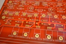
But there is a but friends, I got no bias to one halve of the MJE15004's. I discovered a little mistake on Jims boards, there is missing a little track from the emitter of the middle MJE15032 to the MJE15033 compaired to the original. So I had no bias on connection DRIVE P1. But that was fixed easily with a little wire:
An externally hosted image should be here but it was not working when we last tested it.
An externally hosted image should be here but it was not working when we last tested it.
After fixing this, there was also current from DRIVE P1. Everything seemed to go OK so I pressed the proverbial gas pedal a bit more ;-). Freakin unbelievable how much power it has. I've measured 40 VAC max output across 8 Ohm load!!! I was able dial the DC offset to 0 mV very easy. Bias spread is about 10 mV across the different TO-3 devices. Not bad, I since I have not matched the devices
An externally hosted image should be here but it was not working when we last tested it.
After some testing (it was 2:00 p.m. already) it was time for some music! It's is unbelievable how it sounds, I try to be as objective as possible, but it is so dynamic, so much power. No hiss, no hum, nothing!!! I've set bias to 450 mV right now. Fans are running full speed right now (fan control is not finished yet). For Dutch standards today is pretty tropical, it is about 26 degrees outside and here in house it is almost 33 degrees. But despite of that, the tunnel cooler gets mildly warm.
Glad that it works, and VERY VERY happy that it sounds even better!!!!!!! But there is still a lot of work to be done, because now I know it works I can and thus still have to mount the lot in the cabinet
KSA100
Hello kapla
Thanks for the details of the PCB Jims, had not seen.
I'm riding slowly.
Great project, I hope to get close, rsrsrsrs.
Best regards.
Hello kapla
An externally hosted image should be here but it was not working when we last tested it.
ares
Thanks for the details of the PCB Jims, had not seen.
I'm riding slowly.
Great project, I hope to get close, rsrsrsrs.
Best regards.
No problem Zeca ! Nice to see your build is progressing too!!
Made a little bit of progress this evening. In the original Krell there is a little PCB which functions as groundplane. This little groundplane is attached to the cabinet. It also contains two 10 Ohm resistors which are connected between ground and the capacitors. Unfortunatelly I can't make PCB's. Haven't got the chemicals and a little etching tank to oxidise copper into Cu2+ and thus etching nice tracks. But....... Kaplaars is maybe not that old but Kaplaars knows about old school So I scraped little tracks into FR4 (glass loaded epoxy) single sided PCB plate. I coated the copper with some tin. Results could be worse
! Nice to see your build is progressing too!! Made a little bit of progress this evening. In the original Krell there is a little PCB which functions as groundplane. This little groundplane is attached to the cabinet. It also contains two 10 Ohm resistors which are connected between ground and the capacitors. Unfortunatelly I can't make PCB's. Haven't got the chemicals and a little etching tank to oxidise copper into Cu2+ and thus etching nice tracks. But....... Kaplaars is maybe not that old but Kaplaars knows about old school
So I scraped little tracks into FR4 (glass loaded epoxy) single sided PCB plate. I coated the copper with some tin. Results could be worse An externally hosted image should be here but it was not working when we last tested it.
An externally hosted image should be here but it was not working when we last tested it.
Red PCBs
No luck here and it just adds to the fun I am having building this amp. I have the older Red PCBs, but it is easy to fix, thanks to your eagle eye. I have the bolt bushings and mica film to make the connections nonconductive. Should I also apply white grease? I understand that these MJE15032/33s do not get too hot. So they really don't need a large sized heat sink?Good job David!!! I also got a reply from Jim:
Thank you very much for building the boards with patience and shared your experience with other people. I have checked the board, and it seems to be an error that happened during PCB fabrication, since in the first log of boards ( I built two logs, and the first log was done in 2007 - 2008) there is a link from the track ( right below the transistor MJE15033) to the base lead of this transistor. I need to check with our PCB vendor why this happened. But I thank you for letting me know this otherwise I thought the board is as good as it has to be.
Nice that this mystery is solved
By the way David, there is another thing you have to take into account. Around the holes which are meant to attach the MJE15033/32's to, there is a conductive ring:
An externally hosted image should be here but it was not working when we last tested it.
When you attach a non isolated / non anodised heatsink, which means your heatsink electrically is conductive, chances arise that your heatsink will make short circuit due to a connection with these holes. This holes are connected to the the collectors of all MJE15032/33 devices. Short circuit between the collectors is something you definetely don't want, because your power lines will make short circuit also (V+ and V- are attached to the collectors). So you have to isolate the heatsink from this rings aswell, or use an isolated heatsink. I took no risk, so I chose to remove the conductive layer on the surface around the holes in the front by drilling very carefully the little conductive surface away. Worked like a charm
@Dean: Aha, so you have the red ones too. I thought the blue ones were yours :-D. Hmm, maybe Spurtle is lucky and have his PCB's the tracks aswell.
Aaah, so no luck for you too. But like you wrote, it adds to the fun building a beast like a KSA-100 gives! It is sane to use thermal grease, but I think it is not necessary for this trannies. But, even though the MJE15032/33's will only dissipate about 15 W in total per channel, it does offcourse no harm, so if you have some thermal grease left, I would add it. I used little silicon pads instead, does the same trick. Although, I have to say, the silicon pads conduct heat a bit less than mica + thermal grease. So for the TO-3 devices mica + thermal grease is the best solution (tried for an experiment silicon pads in my class A audio analyse, I could clearly sense the temperature of the TO-3 with silicon pad was higher than the one with mica, so replaced the mica's back).
That is true, you don't need a big heatsink for them. To be fair, I over exaggerated a bit with mine, The heatsink I use is pretty oversized for the task, but I liked the colour
It is sane to use thermal grease, but I think it is not necessary for this trannies. But, even though the MJE15032/33's will only dissipate about 15 W in total per channel, it does offcourse no harm, so if you have some thermal grease left, I would add it. I used little silicon pads instead, does the same trick. Although, I have to say, the silicon pads conduct heat a bit less than mica + thermal grease. So for the TO-3 devices mica + thermal grease is the best solution (tried for an experiment silicon pads in my class A audio analyse, I could clearly sense the temperature of the TO-3 with silicon pad was higher than the one with mica, so replaced the mica's back).That is true, you don't need a big heatsink for them. To be fair, I over exaggerated a bit with mine, The heatsink I use is pretty oversized for the task, but I liked the colour
You seem to be online and will take this opportunity to ask you-what speaker system are you going to use? I am planning to build my speakers as mine are limited to 75w RMS and are quite old-3 way floor speakers. All I need now to finish the Krell are the transformers and can capacitors. Oh, I forgot, a fire extinguisher too.Aaah, so no luck for you too. But like you wrote, it adds to the fun building a beast like a KSA-100 gives!
That is true, you don't need a big heatsink for them. To be fair, I over exaggerated a bit with mine, The heatsink I use is pretty oversized for the task, but I liked the colour
I have an stereo setup with two B&W DM604 S1 speakers which I will use with the Krell clone when it is finished. They are 4 ohm (3.3 ohm dip), 3 way with two big bass drivers, one kevlar mid and one aluminium tweeter. They can dissipate a maximum of 200W. I really like the sound of B&W. Sound is difficult to describe, but when I have to describe the DM604's they produce that warm, so called English sound. Realy nice and tight bass, nice mids and highs. Although, I have to admit, I miss the 3D stage a bit. Every sound comes from one corner. There are a lot of speakers which I've listen to and do this much more better, but that comes with a price. Like the Piega P10, wow, what a sound. If I ever win the national lotery..... these baby's are mine Well baby's, they are 1,20m!
Don't know in which language this is written, but this link shows a picture of the DM604's I own: http://www.avx.hu/forum/uploads/monthly_06_2011/post-22085-098337300 1307621847.jpg
I have also little B&W DM302's which I use when I test an amplifier. Every time I listen to them I am surprised to the complete sound which these little speakers produce. They won the EISA award back in 1997. Well deserved if you ask me.
Actually, the quality of the speaker is far more important than the amplifier for the sound, since speakers will always be the weakest link. Distortion caused by speakers is much higher than a regular, cheap hifi amplifier will ever have.
It is much fun to compare speakers. Every speaker has another sound. I sometimes go on a trip with my uncle to HiFi stores. Last year we went to Amsterdam comparing speakers. Differences between speakers are far much greater than between amplifiers.
Haha and don't forget to have beer when finishing the Krell to celebrate that it works Spurtle!
Well baby's, they are 1,20m! Don't know in which language this is written, but this link shows a picture of the DM604's I own: http://www.avx.hu/forum/uploads/monthly_06_2011/post-22085-098337300 1307621847.jpg
I have also little B&W DM302's which I use when I test an amplifier. Every time I listen to them I am surprised to the complete sound which these little speakers produce. They won the EISA award back in 1997. Well deserved if you ask me.
Actually, the quality of the speaker is far more important than the amplifier for the sound, since speakers will always be the weakest link. Distortion caused by speakers is much higher than a regular, cheap hifi amplifier will ever have.
It is much fun to compare speakers. Every speaker has another sound. I sometimes go on a trip with my uncle to HiFi stores. Last year we went to Amsterdam comparing speakers. Differences between speakers are far much greater than between amplifiers.
Haha and don't forget to have beer when finishing the Krell to celebrate that it works Spurtle!
Last edited:
Speakers
Surprised you are still up and not asleep. It is 7:30PM here in Chicago. Either you're studying or playing around with your Krell. You have a nice week Kaplaars.I have an stereo setup with two B&W DM604 S1 speakers which I will use with the Krell clone when it is finished. They are 4 ohm (3.3 ohm dip), 3 way with two big bass drivers, one kevlar mid and one aluminium tweeter. They can dissipate a maximum of 200W. I really like the sound of B&W. Sound is difficult to describe, but when I have to describe the DM604's they produce that warm, so called English sound. Realy nice and tight bass, nice mids and highs. Although, I have to admit, I miss the 3D stage a bit. Every sound comes from one corner. There are a lot of speakers which I've listen to and do this much more better, but that comes with a price. Like the Piega P10, wow, what a sound. If I ever win the national lotery..... these baby's are mine
Don't know in which language this is written, but this link shows a picture of the DM604's I own: http://www.avx.hu/forum/uploads/monthly_06_2011/post-22085-098337300 1307621847.jpg
I have also little B&W DM302's which I use when I test an amplifier. Every time I listen to them I am surprised to the complete sound which these little speakers produce. They won the EISA award back in 1997. Well deserved if you ask me.
Actually, the quality of the speaker is far more important than the amplifier for the sound, since speakers will always be the weakest link. Distortion caused by speakers is much higher than a regular, cheap hifi amplifier will ever have.
It is much fun to compare speakers. Every speaker has another sound. I sometimes go on a trip with my uncle to HiFi stores. Last year we went to Amsterdam comparing speakers. Differences between speakers are far much greater than between amplifiers.
Haha and don't forget to have beer when finishing the Krell to celebrate that it works Spurtle!
What are these groundplanes used for? For what capacitors?No problem Zeca
Made a little bit of progress this evening. In the original Krell there is a little PCB which functions as groundplane. This little groundplane is attached to the cabinet. It also contains two 10 Ohm resistors which are connected between ground and the capacitors. Unfortunatelly I can't make PCB's. Haven't got the chemicals and a little etching tank to oxidise copper into Cu2+ and thus etching nice tracks. But....... Kaplaars is maybe not that old but Kaplaars knows about old school
An externally hosted image should be here but it was not working when we last tested it.
An externally hosted image should be here but it was not working when we last tested it.
Surprised you are still up and not asleep. It is 7:30PM here in Chicago. Either you're studying or playing around with your Krell. You have a nice week Kaplaars.
Haha, well I am a bit like the Djungarian hamster; awake at night
It was 2.18 a.m. (I realise right now I mixed a.m. and p.m. up in previous posts) in Holland at that time. But right after that, I got to sleep. I will use by the way one groundplane. The little one in the picture with the two resistors. In the originall Krell the centertap is not connected directly to the chassis, but there is a resistor in between (R405 in the schematic below).
An externally hosted image should be here but it was not working when we last tested it.
If I understand right the resistor has a function to damp 'mess' that walks into the amplifier via GND. By the way, when making a groundplane you have to choose resistors that can dissipate a few watts, 5 or so, so that is does not function as a fuse when there is short circuit to GND.
Spurlte, these 10 ohm resistors go between ground and chassis...one for each channel...
one are better of using 10ohm NTC, like CL-60 insted of resistors.
Schematics works so will, doesn't it? "To damp 'mess' that walks in the night. Very well put. So it bring a point I need to resolve. Which ground do you use to shield inputs and outputs? My tube preamp's transformer is not center tapped.
Yes, creepy nightwalkers are not allowed in my amplifier ;-) Only joking, but the resistors should damp distortion which can travel via GND into your amplifier bit.
I use star ground. All the devices that have to be connected to ground, like the shield around the signalcables, the minus leads of the speaker terminals, earth GND from the wall outlet and so on are connected to the little groundplane. The little groundplane itself is connected to the chassis. So actually all ground leads come together in one point. This is what is called star grounding. Correct grounding is VERY important for a stable, hum free amplifier. Here is some more interesting info: Earthing (Grounding) Your Hi-Fi - Tricks and Techniques
- Status
- This old topic is closed. If you want to reopen this topic, contact a moderator using the "Report Post" button.
- Home
- Amplifiers
- Solid State
- Stolen Trademark Amplifier from Jim's Audio on EBAY