Another comment on this topic of capacitors: When I was modifying the design of a power amp (a switcher, but that's actually not significant) I was able to eliminate the coupling capacitors in the signal path altogether, save the "indirect" effect of two caps associated with the d.c. servo. I tried my best to not require that the servo work too hard, but it had to accommodate variations in the input JFET stage as well as some presumed small offset voltage in the source.
Although one can hardly be objective when listening to one's own designs, I was pleased with the results. But I realized that another feature was a possible contributing factor: the input resistance was set rather high, to 1 megohm. This has the effect of making the presumptive output coupling caps in most sources have relatively smaller signal voltages across them, and their propensity for introducing audible artifacts correspondingly smaller. Of course the noise with an open input will be higher, but this is hardly relevant to actual applications.
Although these amps were designed for internal use in dedicated systems, two people wanted to test them before a trade show, and I wasn't there to see them hook them up. For some reason it didn't occur to them that using clip leads to attach the source to the amp was not a good idea, and they promptly smoked the output Zobel network as the amp broke into oscillation due to input-output coupling.
This drove a design change so that the amps would shut down when the Zobels sustained a lengthy overload. That little board got crowded by the end.
Hi bcarso,
You have just done a great job of articulating why I really like DC servos combined with JFET input stages. The ability to have a high input impedance for the amp is a keeper.
Cheers,
Bob
I made my first BIG mistake using capacitors in 1970, designing a solid state studio board for the GD. We had already chosen the highest quality IC that we could find: The Harris 911, that could operate at +/- 24V, drive 600 ohms, and had the slew rate of +5/-2.5 V/us. Pretty darn good for an IC at that time. My associate found some 2uf CERAMIC caps that were the right size for coupling between stages. We built the board, it tested OK, (at the time I only had an SMPTE IM analyzer) and an 80 MHz scope. Still, it seemed to work OK.
However, when it was evaluated by the GD over a period of time, they went back to tubes, and I went back to being unemployed. This taught me a serious lesson. Designing like an engineer, and meeting traditional specs, did NOT necessarily make an acceptable audio product. Later, much later, like a few years later, I realized that the CERAMIC caps, and secondarily the IC's, had ruined the audio quality, and I COULD NOT measure the problems with the test equipment that I then had very well.
However, when it was evaluated by the GD over a period of time, they went back to tubes, and I went back to being unemployed. This taught me a serious lesson. Designing like an engineer, and meeting traditional specs, did NOT necessarily make an acceptable audio product. Later, much later, like a few years later, I realized that the CERAMIC caps, and secondarily the IC's, had ruined the audio quality, and I COULD NOT measure the problems with the test equipment that I then had very well.
While I switched back to discrete designs, for the most part, in 1972, the cap question was still 'unresolved'. It was just presumed that caps behaved OK, for the most part, and that you could believe the spec. sheet. I still made some mistakes, like making passive active xovers with tantalum caps, but I avoided the large ceramic caps, almost accidently.
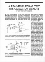
However, in 1974, while visiting Tektronix, I was shown an experimental design that measured CAPS, by making a modification of a Tek 577 curve tracer. The design was originally developed to measure the capacitance, but it was found that SOME caps, especially large CERAMICS, did something very odd when the measurement was attempted. They just did NOT trace within the normal parameters expected of a capacitor. They showed VERY different behavior, including 'non return to zero', and huge changes in capacitance with voltage. Where was this on the data sheet? Why were we not warned? In any case, it was a breakthrough for me, because it was the first time I saw a measurement that actually showed that caps were not completely free of distortion. (more later)
However, in 1974, while visiting Tektronix, I was shown an experimental design that measured CAPS, by making a modification of a Tek 577 curve tracer. The design was originally developed to measure the capacitance, but it was found that SOME caps, especially large CERAMICS, did something very odd when the measurement was attempted. They just did NOT trace within the normal parameters expected of a capacitor. They showed VERY different behavior, including 'non return to zero', and huge changes in capacitance with voltage. Where was this on the data sheet? Why were we not warned? In any case, it was a breakthrough for me, because it was the first time I saw a measurement that actually showed that caps were not completely free of distortion. (more later)
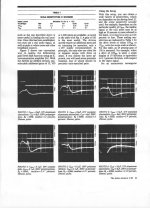
Once, I KNEW that large value ceramic caps were a real problem, I tried to measure them, as well, with more conventional audio equipment, like with an IM analyzer or a wave analyzer. I found that IF I dropped some AC voltage across the cap then both large value ceramics and tantalum caps could show quite a bit of measured distortion. It was just a matter of setting the test frequencies and load resistor so we were at the edge of where the cap actually rolled off.
Last edited:
Moving in circles, look please side about 1502-1503in this thread, debate about using capacitors for coupling about year ago.... What are you shoving, is not coupling, but filtering, with relatively big AC voltage across capacitor. If you use bad component ( ceramic or tantalum..) in bad aplication, you get bad results. Nothing surprising.
Last edited:
Well, BV, live and learn! '-)
It is interesting that my two cap distortion examples came from close enough models of HOW we designed amps and preamps at the time. In fact, most of you still design the way we once did, given many examples shown on this website. I hope to open up alternatives to this design approach, like we do today, and not 30+ years ago.
It is interesting that my two cap distortion examples came from close enough models of HOW we designed amps and preamps at the time. In fact, most of you still design the way we once did, given many examples shown on this website. I hope to open up alternatives to this design approach, like we do today, and not 30+ years ago.
I am learning,") .
.
Measurements of line preamp (all bipolars),more coupling capacitors in signal path, instead of servos, volume regulation with relays and L pads. No "capacitor" distortion, excellent sound.
.Measurements of line preamp (all bipolars),more coupling capacitors in signal path, instead of servos, volume regulation with relays and L pads. No "capacitor" distortion, excellent sound.
Last edited:
Congratulations BV, you did make great specs with a sine wave.
Non-linear distortion aside, my next topic is Dielectric Absorption in capacitors, which is almost impossible to notice with AC measurements.
This became studied by audio designers just about the time that I gave the paper cited above. It just so happens that it was Richard Marsh who introduced it to the audio community in an LTE to 'The Audio Amateur' or TAA about the same time period of the late 70's.
DA was NOT an unknown topic, but it seemed relatively unimportant to audio, until Richard Marsh started testing for it. Then, it became an interesting audio deviation to measure in capacitors for the next several years. (more later)
DA is possible only with AC voltage across capacitor, it is possible only if too low capacity value is used . In measurements posted about one year ago, electrolytic capacitor used for coupling for real, music signal, caused non measurable change (diference to direct path). But DA for same capacitor is clearly measurable. Once again, DA is not a problem for capacitor with big enough value (so AC remain negligible) used for coupling for audio signals and caused no detectable change (for measuring or for ears, too.) for any signal (sine, music, square, noise..) in audio band. But DA is clearly problem for capacitor in frequency filters with "non zero" AC voltage . And THD (IMD, SPMTE..) distortion rise with decreasing frequency (and increasing voltage across capacitor- DA influence) is clearly detectable with AC measurements. YOU alone did it, many times, e.g. in last picture you posted. And "specs" remain the same for sine or for music...
Last edited:
Congratulations BV, you did make great specs with a sine wave.
Non-linear distortion aside, my next topic is Dielectric Absorption in capacitors, which is almost impossible to notice with AC measurements.
This became studied by audio designers just about the time that I gave the paper cited above. It just so happens that it was Richard Marsh who introduced it to the audio community in an LTE to 'The Audio Amateur' or TAA about the same time period of the late 70's.
DA was NOT an unknown topic, but it seemed relatively unimportant to audio, until Richard Marsh started testing for it. Then, it became an interesting audio deviation to measure in capacitors for the next several years. (more later)
It is important that -at the time - we had to listen more to get clues as to what we should measure. Sim programs were too crude at that time and would be too expensive - we didnt have cheap, powerful PC's at all. Listening tests indicated that my research showed that a characteristic called DA could produce sound that was closest to what was heard when poor DA caps were used. So, that led to further research and a test instrument I designed and showed on a scope waveform that DA had real audible consequences. Later, I gave an invited talk to describe the development of audible waveforms not indicated with tests using symetrical waveforms (sine waves). I showed how the extraneuos waveform was created on the black board. And, had done FFT on the extracted - unwanted - waveform from DA effect which showed primarily second harmonics (used a LeCroy scope with built-in FFT). Something I have never talked about since. But, note that sine waves will not show the problem. That talk was at WESCON in San Jose and was well recieved by the heavi-weights in the IC design and other researchers in the audience. I suggest more audio designers try listening and calibrating your ears as another tool. - Thx - Richard (Dick ) Marsh
Last edited:
Soon, we will TEST that hypothesis, BV. But first, let's talk a little about DA, what makes it DIFFERENT from non-linear distortion, and how it can be present in caps that show very little, in fact, almost unmeasurable non-linear distortion and yet can measure many % linear distortion, WITH THE RIGHT TEST SIGNAL.
First, DA used to be very important in calculation, before digital computers got powerful enough to replace them. Back in the '50's ANALOG COMPUTERS were mostly used to solve differential equations that would be difficult to do by hand, or calculator.
These computers used OPERATIONAL AMPLIFIERS, you know, what we call most linear IC's, today. It was difficult in those early days to make an operational amplifier from just tubes, but they did so. Later, solid state amplifiers were made with the new semiconductors being made, and this was the start of many companies still famous today, even though they now only make IC's.
In the case of the operational amplifier, the fundamental control parts are actually the PASSIVE PARTS that are used around the gain block that normally looks like a triangle.
They knew this in the '40's at the very least, and some of the best papers ever written on DA were generated in the early '50's, because that is when analog computers were dominant in solving a number of problems that could be expressed in mathematics, but were difficult to solve, and get a useful answer. Usually, a graph of motion over time.
We have virtually discussed RESISTORS to 'death' on this website, but CAPACITORS, when used as control elements for analog computers, were a real liability in getting 'accurate' results. DA was one of the prominent problems that showed up, and this is why, almost always, polystyrene or Teflon caps were used with these computers. Even Mylar was not good enough for serious work. (more later)
I thought we established some time ago (possibly even in this very thread?) that DA itself cannot create distortion as it is a linear phenomenon. However, high DA may possibly be a useful marker for some other nonlinear dielectric problem which can create distortion. Were we wrong, or did I misunderstand?
Thanks RNM,
One of the issues is that Cdv/dt + Vdc/dt = i. Allowing dc/dt due to voltage to be almost zero that term drops out. (dc/dt due to vibration can be a different story.)
Since audio capacitors are in series with some resistance, the output voltage is of course i/Rload. Now for dv/dt of a sine wave the i(t) is a cosine so there appears to be no distortion. However any waveform where dv/dt is not the same there will be distortion. So sine wave testing of these kinds of distortions yields false results. I mentioned this way back in the thread and everyone jumped on the Fourier bandwagon. As I didn't want to get into the limits to Fourier transforms (Just for the guys who want to try that, just model a record scratch completely!) and the real world.
ES
As I didn't want to get into the limits to Fourier transforms (Just for the guys who want to try that, just model a record scratch completely!) and the real world.
ES
This sounds interesting. Would you elaborate on the limits of the Fourier transform ?
Also what do you mean by "model a record scratch completely" ?
Last time I looked, differentiation and integration were linear transformations so can't introduce distortion. They do, of course, modify frequency response. Sorry, am I "jumping on the Fourier bandwagon"? Silly me, to think that mathematics might actually tell us something useful about "the real world"!
Let's instead, use another waveform that does not look like a sine wave or two.
Let's use a BANDWITH LIMITED PULSE, that is of a fixed duration, asymmetrical, and has a long resting period between pulses. We did a lot of experimenting, yet we found that the pulse length originally selected by Scott Wurcer, was about as good as anything else, better than most, in fact and still within the actual WORKING bandwidth of audio systems.
Let's use a BANDWITH LIMITED PULSE, that is of a fixed duration, asymmetrical, and has a long resting period between pulses. We did a lot of experimenting, yet we found that the pulse length originally selected by Scott Wurcer, was about as good as anything else, better than most, in fact and still within the actual WORKING bandwidth of audio systems.
- Status
- Not open for further replies.
- Home
- Member Areas
- The Lounge
- John Curl's Blowtorch preamplifier part II