Despite their diy unfriendliness SM devices do enable some significantly higher-performance designs, even for mostly-discrete components --- wonderful though the achievements of modern integrated circuits may be, and certainly the only alternative for seriously high frequencies.
If I could persuade my former employer to let me cart off the spectrometer, the finishing refinements on which date back to about 1981, I'm sure I'd be amused to see how I managed to get performance out of what today look like hideously large components, the smallest of which were TO-18 and TO-72 metal case devices. Construction was point-to-point on two-sided-copper-clad boards, with some connections made with bus wire and teflon tubing. Although clock driver speeds probably didn't need to be as high as was managed, it was fun to see how well things could be made to work. At one point in the development, with some subassemblies already complete and functional, some end-of-year money appeared and got spent on a 200MHz scope and 900MHz active probe. I suddenly could see a lot of fine structure everywhere and this drove significant modifications, as well as additional delays which further endangered my employment.
When the instrument was first powered up of course it didn't work. But two weeks later it did, this after about four years of design and construction. The word on the street was It will never work (enemies) and It will take a year at least of debug (friends). Some of the enemies finally amended their story to Well maybe it will work for a while.
Is that the ones I heard at your house? If so, they were surprisingly good.
No, you heard arrays made each with 24 drivers from police motorcycles. If some audiophile magazine knows that they would sing Anathema to Wavebourn.

Last edited:
The numbers are 5-10x less on todays SMT packages OTOH we are trying to make 10G TIA's. If you check the AD8010 datasheet you will see a bypassing scheme that was necessitated by bond wire mutuals, that gets pretty amazing diff gain and phase with lots of parallel video loads.
Any of it BGA/flipchip, or do they all have wires?
Thanks for the offer. Copper is kinda pricey.. we take the cuts and send them off to recycle, ours go 12/2 up to 535kcmil, but never longer than 2 or 3 meters.If you ever need any small quantities, let me know I still have scraps left over. Normally we get "Thick" triax on 3500' put ups for stadium use. Any length under 300' is scrap.
Although with the high price of scrap we actually are getting rid of some of it.
j
(**)Talk about God existence (hypothesis)
Besides, both men were long dead by the time things were becoming hot with aether-based valid electromagnetic theories.
Not to belabor, but when I was traveling to college way back then, one morning my car would not start, not even a solonoid click. Had 6 hours to drive.
Put jumper cables on, tried three times and not even a click, so turned key off position for 4th time. Waited a couple of minutes, prayed to God, said Amen, and heard something. Looked over and the engine was cranking like crazy. So reached inside, turned the key to on position, and engine started. No starter motor grind, problems etc. Drove to college, parked it and never tried starting it again. Sold it for 70 bucks.
Back to the subject at hand. Let's see if we can reach 3 million hits.
Cheers.
Last edited:
Any of it BGA/flipchip, or do they all have wires?
Thanks for the offer. Copper is kinda pricey.. we take the cuts and send them off to recycle, ours go 12/2 up to 535kcmil, but never longer than 2 or 3 meters.
j
BGA often has a die bonded to a substate but we can put the solder balls right on top of active silicon and flip the whole thing directly onto the board, 3D chip stacking too. Packing density and power are the biggest concern these days, some of this stuff is crazy.
350KCM is the next step up on 4/0, probably only needed for your 1 Ohm speakers.
I once looked through a battery/cable catalog for electric locomotives, the shipping will kill ya.BGA often has a die bonded to a substate but we can put the solder balls right on top of active silicon and flip the whole thing directly onto the board, 3D chip stacking too. Packing density and power are the biggest concern these days, some of this stuff is crazy.
And the beauty of BGA is that you can mount it on a ceramic substrate like kyocera, with embedded supply bypass caps. I used the kyocera ceramic stuff back in the late 80's, it was only available in purple. Now, I get kyocera knives...holy mackeral, are they sharp. They don't hurt even when the blade makes it to the bone.. I knew it happened, looked at my finger, said two things...one, the owner of that finger now has the name "you f'in idiot.. and two...that''s gonna hurt.
I was correct on both counts..
That's weird. I have 350 widgits being connected using 262kcmil cable, about 15 thousand feet. But the cable we are using is DLO, I guess that has different guages.350KCM is the next step up on 4/0, probably only needed for your 1 Ohm speakers.
But man, you should see the subs..
j
There's so much of the universe to explore and waiting millions of years for answers is not an attractive prospect.
On the contrary my friend. It is just because of this that the prospects are attractive. Even the probabilities are positive ( The one hand bandit hasn’t given coins for some time now).
Enjoy the flavors of one of your wines, and wait for a new burst of knowledge, like the ends of 19th century.
(very romantic!)--------------------------------------
Simon, is it you with the binoculars on the picture?
--------------------------------------
For old style chips … Home made triaxial cable.
j
Jneutron
That was disappointing. Hardly 220 words. Are you O.K. ?
Thank you (especially for the center of elipsoid part on your prior posts)
As I read it, you target the problem at the bonding wires and pads. That’s in agreement with Scott words.
This I find strange. I mean how all the routing within each layer and the stacked layers between them end up less troublesome than the bonding wires.

Usually an L/R/C extraction (with mutuals) from conventional methods is OK for normal IC's (100MHz or so).
Scott, I hadn’t noticed your response, sorry.
Now, to exercise your patience, one more step on the ladder:
Why these “conventional methods” brake up above say 100MHz?
Is it that the conception of L/R/C can not model the reality anymore, and if so, why?
(I guess the next floor is a few more steps higher, so prepare yourself
)Not to belabor, but when...
Had you had hammered once or twice directly on the starter’s solenoid, you wouldn’t have to pray.
(Usually this activity is accompanied with shouting out some words not appropriate for a religious man)
George
Not to belabor, but when I was traveling to college way back then, one morning my car would not start, not even a solonoid click. Had 6 hours to drive.
Put jumper cables on, tried three times and not even a click, so turned key off position for 4th time. Waited a couple of minutes, prayed to God, said Amen, and heard something. Looked over and the engine was cranking like crazy. So reached inside, turned the key to on position, and engine started. No starter motor grind, problems etc. Drove to college, parked it and never tried starting it again. Sold it for 70 bucks.
This seems apropos.
Matt the Electrician "For Angela" - YouTube
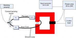
I sure would like to know where the higher order harmonic distortion is generated, if it is not the wire-cable system, itself.
I do not know how a 'ground loop' could cause higher order harmonics distortion as of yet. Might pickup hum/noise, but harmonic distortion? And why do many cables not have much if any, higher order harmonic distortion? Yet others have it repeatedly.
Maybe it has something to do with the 'Centroid'. '-)
I sure would like to know where the higher order harmonic distortion is generated, if it is not the wire-cable system, itself.
I think it's pretty clear it's generated by your antiquated ST-1700.
I sent you and Bruno identical sets of cables. You showed distortion on your ST system while there was no distortion on Bruno's AP system.
Time to donate that thing to a museum and have Parasound buy you a nice AP rig.
se
For the record, Steve, the cables with the exception of one, had NO harmonics in my test. While I think that your wire selection was reasonable, you 'lucked out' with really low residual measurements.
However, MY cables can bring it out, even IF they appear similar to your cables in construction or brand.
However, MY cables can bring it out, even IF they appear similar to your cables in construction or brand.
For the record, Steve, the cables with the exception of one, had NO harmonics in my test.
NO, there is no ringing. It is harmonic distortion.
OK, you've now confused me.
(cue Ed to show effects of slight amounts of contact resistance in a ground loop)
edit: FWIW, when John showed me his setup, we saw low level harmonics of the test signal, consistent with jneutron's clear analysis.
yah know, I am feeling a tad under the weather..Jneutron
That was disappointing. Hardly 220 words. Are you O.K. ?
Thank you (especially for the center of elipsoid part on your prior posts)
I'll try better next time..
On chip, the physical size is significantly smaller, and the chip designer has absolute control over interconnect lengths, dielectric thickness, characteristic impedance, parasitic inductances. But to get to the outside world requires big things with big parasitics. Then, on the pc board, the designer can do the same thing to control the characteristics. But at high slews, the chip to board interface is indeed one of the bottlenecks. That is why flip chip and BGA exist...that, and of course, "No user serviceable parts inside, please refer servicing to qualified personnell"...As I read it, you target the problem at the bonding wires and pads. That’s in agreement with Scott words.
This I find strange. I mean how all the routing within each layer and the stacked layers between them end up less troublesome than the bonding wires.
I sure would like to know where the higher order harmonic distortion is generated, if it is not the wire-cable system, itself.
I do not know how a 'ground loop' could cause higher order harmonics distortion as of yet. Might pickup hum/noise, but harmonic distortion? And why do many cables not have much if any, higher order harmonic distortion? Yet others have it repeatedly.
Maybe it has something to do with the 'Centroid'. '-)
It absolutely does have something to do with centroids.
I repeat...what you have is a system which has a frequency dependent path structure. The ground loop is directing the current based on the loop characteristics and the frequency. Change the cable, what the receiver sees changes. It's a variable crossover setup John, one where you have no control over the break frequency.
Look at the analysis jcx was kind enough to run. Every frequency you look at is already above the point where a simple pc board loop has started to shift current due to proximity..
You have no control over where the currents at any frequency are going. Nada, none, zipp...
That's why your results cannot be used to explain cable distortion, nor invoke new physics.. (edit:see ps below)
Fix the setup.
Oh, for everybody else, I will repeat what I told John over a decade ago (IIRC).
The fact that JC's test setup is inadequately designed to test at the level he is attempting to see is IRRELEVANT to me. I do not care.
What is important is the lessons we can learn.
1. Always question one's results, especially if they coincide with one's beliefs. They may be wrong, and allow you to continue down an incorrect path.
2. In general, you may be the best person to question your own beliefs and understandings, as you are the worlds expert in what you think. We are poised to be our own best critic.
3. A bad test setup such as that JC has created, is not inconsequential nor a waste of time. What he has found is a measure of how a bare cable alters the test outcome where one would never expect a difference.
In summary, JC's work is high caliber, well thought out in many respects, beyond that which was done or thought of at the time, and an extension of knowledge. It is to be lauded.
ps... EDIT: HOWEVER, YOUR RESULTS ABSOLUTELY CAN BE USED TO DEMONSTRATE AND EXPLAIN how an interconnect cable or power cable can affect the sound of a system despite the fact that it uses linear materials.
pps. this test (attached) spots ground loop susceptibility of equipment(the driving iron structure is red because the actual hardware was that color). This needs to be incorporated into the world of high end and pro audio..you up for it, or would you prefer to be a passenger??
j
Attachments
Last edited:
SY,
It is not the bad ground connection, it is the soft dielectric used for insulation that makes the cables I looked at different. Cue to you about tapping on capacitors!
When my shaker table test that shows V dc/dt effects from capacitors is used on cables the results go through the roof. Which is even more impressive when you realize how little actual capacitance you have to start with. At .01 G (Gravity) dc/dt can be in the low whole number percent range for particularly bad cables.
Scott ignore all this it really is micro-diodes. (NOT!)
Steve, the distortion of actual wires as shown by my tests is below the resolution of an AP system 2 as used by Bruno. J.C. uses an ST1700 as a filter to feed an FFT analyzer. Not having tried an ST1700 at all I have no useful knowledge about the capabilities.
In my tests I can get the same results on different days and in front of semi-knowledgeable observers. (J.J., D.S., R.S. and others.)
ES
It is not the bad ground connection, it is the soft dielectric used for insulation that makes the cables I looked at different.
1. The change in capacitance of a coaxial structure where the core is moved with respect to the shield is very very low. We attempted to use that set of equations to make a capacitance meter for seeing liquid nitrogen in a outlet port of the atlas project for the LHC. We were worried that physical displacement of the inner core as a result of cooling to 77k would alter the measurement, but were shocked to see how little effect there was both in calculation and measurements.
2. Soft dielectric can indeed give off charge in compression, especially if it is pre charged.
3. Small core movements within the coax cause movement of the core centroid away from the shield centroid. When that happens, two things result. First, inductance external to the coax shows up due to the loss of symmetry. Second, there is now a loop area, and you are moving the cable in an environment which has anywhere from .5 to .7 gauss, depending on where on the planet the test is performed. Mu metal shielding will work at this field level, but you'd have to degauss the structure before test.
I would recommend you have this stuff reviewed for accuracy before publishing...I see significant holes.
j
- Status
- Not open for further replies.
- Home
- Member Areas
- The Lounge
- John Curl's Blowtorch preamplifier part II