It looks like TI has been busy since taking over NS. They have finally given us something we always asked for, spice models for the LMxxxx series (Overture) chip amps!
Check out the product pages at TI.com
Speaker Amplifier and Modulator - Mid/High-Power Amplifier - LM3886 - TI.com
Speaker Amplifier and Modulator - Mid/High-Power Amplifier - LM3875 - TI.com
Speaker Amplifier and Modulator - Mid/High-Power Amplifier - LM4780 - TI.com
etc.
The pspice models are near the bottom of each page. Based on the file dates, these were only just released this past March/April. Generally, pspice models are easily adapted to (free) LTSpice. While some amateur attempts have been made to create models, they were simplistic and did not accurately represent the behavior of the real part. A comment from the TI-produced LM3886 pspice model states:
This seems to cover the important operational parameters and should, hopefully, give reasonably accurate simulations.
I'll work on drawing a LM3886 .asy (schemtic symbol) to go with the model, and then try to get a sim running in LTSpice. I'll post any results here.
Check out the product pages at TI.com
Speaker Amplifier and Modulator - Mid/High-Power Amplifier - LM3886 - TI.com
Speaker Amplifier and Modulator - Mid/High-Power Amplifier - LM3875 - TI.com
Speaker Amplifier and Modulator - Mid/High-Power Amplifier - LM4780 - TI.com
etc.
The pspice models are near the bottom of each page. Based on the file dates, these were only just released this past March/April. Generally, pspice models are easily adapted to (free) LTSpice. While some amateur attempts have been made to create models, they were simplistic and did not accurately represent the behavior of the real part. A comment from the TI-produced LM3886 pspice model states:
Code:
* The LM3886 Macro Model represents the following parameters for
* split-supply operation (+/-28V):
* GBWP, input-referred voltage noise, the quiescent current,
* output swing, input offset voltage, input bias current, PSRR,
* CMRR, and the slew rate.I'll work on drawing a LM3886 .asy (schemtic symbol) to go with the model, and then try to get a sim running in LTSpice. I'll post any results here.
Last edited:
Thanks for the heads up. I downloaded it and tried to run a sanity check in LTSpice with a basic inverting gainclone circuit, and something is broken - it produces a tiny sinusoidal signal of some nV at the output.
I'll recheck the .asy file and the pin order again. The same inverting gainclone circuit works fine with Pedja's LM1875 and Teemuk's older LM3886 model, so it's something specific to this model file that's broken in LTSpice. LTspice isn't complaining about anything in the model, though - it runs the transient analysis, but incorrectly.
Edit: MUTE behaviour is broken, i.e. inverted. It now works when I leave MUTE floating (unconnected). If I pull it down to Vee with a 10k resistor, the output shuts down - there's a 60 nV signal at the output. It's bit late here now to debug and fix, so I'll leave it to somebody else to confirm this behaviour - the fix should be fairly simple.
Last edited:
I have confirmed the mute behavior, when pulled down to -Vee, the output is muted. When left floating, the output is enabled.
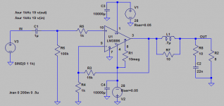
I have attached a zip with an LTSpice "asy" file which contains a schematic symbol for LTSpice, as well as an example schematic. You will need to download the pspice model from TI and put the LM3886.lib file in the same directory as the .asc and .asy files.
The distortion (refer to simulation error log) seems a little low at 0.000053%. Don't forget to turn of 1st/2nd order compression and ensure the simulation runs for an exact multiple of the input waveform period when testing distortion. The input waveform distortion is also tested; this is used to ensure that the simulation is working well enough. If the distortion of the sine source signal is not nearly zero, then your sim is broken need to tweak something.
Attachments
Last edited:
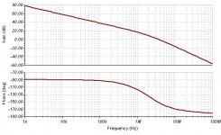
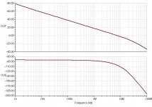
Cool - I noticed that the distortion was unreasonably optimistic. THD20 FFT showed all harmonics at -170 dB or below, for an output amplitude of 18V into 8 ohms. Probably a pure behavioural (polynomial) model, not a structural model for the output stage. AC small-signal corner frequencies seem to be sane, so it probably models the poles/zeroes correctly - it should be ok for stability/phase-margin analysis, though maybe not for distortion analysis.
MyRef Rev C and Rev E schematics seem to work in transient analysis (I use a modified LM318 model to take care of the Comp pin), though of course the THD20 numbers will be suspect.
Still, it's good to have this model to cross-check with the earlier unofficial models.
MyRef Rev C and Rev E schematics seem to work in transient analysis (I use a modified LM318 model to take care of the Comp pin), though of course the THD20 numbers will be suspect.
Still, it's good to have this model to cross-check with the earlier unofficial models.
Distortion of opamp spice models is NEVER assumed to be realistic, this also stated in most any serious model file.
But the real bummer is elsewhere. I did a quick check and found that that the bode plot is completely off, indicating a unity stable amp and in fact it sims like this in a transient analysis (WTF!). GBWP is set to datasheet max of 8Mhz, not 4Mhz (typical for the real part). Open-loop phase hits 120deg at over 10Mhz, while in reality and datasheet this point is at below 1Mhz.
For correct AC analysis and stability checks the model seems to be useless.
EDIT: see my take on a correct bode plot estimation here.
Obviously nobody at NS/TI checked the model, otherwise the "mute bug" and the wrong gain/phase response would have been readily detected BEFORE publication.
All in all I'm not impressed.
Last edited:
For correct AC analysis and stability checks the model seems to be useless.
EDIT: see my take on a correct bode plot estimation here.
Oh, well - not much use for the model then. It looks fairly elaborate, too, with lots of sub-circuits, etc. Would you consider it worthwhile to incorporate your AC model into it, or is the TI model just too broken/complicated to try to save?
Yeah, the model is very complicated, most probably it was generated by some automated tool. It is a behaviouristic model, no actual transistor are involved.
I already did try to find the hot-spot for the AC behaviour by looking for capacitors which could define the poles but that was unsuccsesful as of yet. It could of course be that it is only an issue with LTspice, but then again LTspice definitely is pretty much the industry standard SPICE simulator (some VLSI chip designers I know normally use the ultra-professional Cadence simulator as their main tool but still resort to LTspice for many smaller simulation tasks).
I'm inclined to think that we must drive TI to fix it inspite of the disclaimer "The model is provided solely on an "as is" basis. The entire risk as to its quality and performance is with the customer." So they are basically saying that even when the model is as screwed as it is, rendering circuits that will be non-functional with a 100% certainity, it is our own fault and sillyness to have trusted their model?
Attachments
I've just downloaded the LM3875 model from the site and run a simulation using 'TINA' which uses the normal SPICE 3F5 engine. (LT SPICE uses some unusual proprietory SPICE engine as far as I know).
The model I downloaded is dated 19th April 2012. (V2.0)
I used the schematic from the app note (non-inverting, gain of x21 into an 8 Ohm load.
For a 1V rms input 1kHz sinewave the distortion is 0.039% which seems reasonable.
The model I downloaded is dated 19th April 2012. (V2.0)
I used the schematic from the app note (non-inverting, gain of x21 into an 8 Ohm load.
For a 1V rms input 1kHz sinewave the distortion is 0.039% which seems reasonable.
^^ Thanks.
I contacted TI, now that we know that TINA also shows the problem.
Faulty SPICE model of LM3886? - Audio Amplifiers Forum - Audio Amplifiers - TI E2E Community
I contacted TI, now that we know that TINA also shows the problem.
Faulty SPICE model of LM3886? - Audio Amplifiers Forum - Audio Amplifiers - TI E2E Community
With model "PSpice" Work and AC analysis set:
http://www.diyaudio.com/forums/attachment.php?attachmentid=282881&stc=1&d=1337346278
Oh-Oh, my fault. It appears that the MUTE function is muted when the pin is floating, and un-muted when >1mA is taken out of the pin. This seems strange, as if it were the other way round you could apply an automatic mute at power-up by connecting a large-value cap between the MUTE pin and 0V
"Mute Function: The muting function of the LM3886 allows
the user to mute the music going into the amplifier by draw-
ing less than 0.5 mA out of pin 8 of the device. This is
accomplished as shown in the Typical Application Circuit
where the resistor RM is chosen with reference to your
negative supply voltage and is used in conjuction with a
switch. The switch (when opened) cuts off the current flow
from pin 8 to V−
, thus placing the LM3886 into mute mode."
Also the function is clear from the internal schematic. The main diff-amp is OFF when the MUTE pin is left open, while the auxiliary diff-amp is ON.
EDIT: Cross-post, I see.
In fact I like the MUTE and STANDBY features of the TDA7294 much better than the slightly akward MUTE of the LM3886.
Last edited:
see my take on a correct bode plot estimation here.
Would you post the .asc file containing your LM3886 model?
- Status
- This old topic is closed. If you want to reopen this topic, contact a moderator using the "Report Post" button.
- Home
- Amplifiers
- Chip Amps
- TI has new spice models for LM3886 LM3875 et all