It's irrelevant w/respect to driver slew rate. rp doesn't enter the picture, only stage standing current. See this if you have any questions.
This is wrong and a common misunderstanding of driving a load. The capacitance that exsists must be charged and discharged and this requires the minimum amount of current, but the impedance of the driving source will produce a divider just as any RC-terms in a filter and give bandwidth limitations even if the standing current is much higher than required.
The reason drivers using higher currents slew grids faster isn't b/c of more standing current, it is b/c to have more current, the resistor values must be lower, and the rp of the tube goes down as ip goes up, so you are driving the load with a lower impedance.
'Wimpy' driver mentioned in the start sound good perhaps b/c:
1. The 2A3 is simply an easy tube to drive. Altho you need relatively high amplitude swing, the low gain gives low miller.
2. There really isn't much > 10kHz we hear.
3. In the old days did the source material include anything > 10kHz? So engineers simply didn't need higher BW.
4. Without loop NFB, and perhaps poor BW in the O.T. what does it matter?
5. They probably found the amp to sound nice as is, why fix it?
6. HiFi hadn't come to the point of nit-pickn everything to death, it was more important to use good engineering and produce something that could sell in the market of the day.
My guess.
I am designing an amplifier with Gu50 tube as a triode . It is as close as I can get to PX25 or 2A3 .
I hope to drive it with 3.5 to 10 mA from a UL connected EF 184 ( say triode , like ECC81 if so ) . Do I need a cathode follower in addition ? I hope my diversion is OK ? There is 0.22 uF between tubes and perhaps a bit of anode to anode feedback . No global feedback , a bit of Pye Mozart Gu 50 cathode feedback perhaps ?
Sorry to butt in . It would help me . A friend has 2A3 / 211/ 845/ 813 . I am sure I can borrow a pair . I have been entered into a competition in Berlin with this amp ( November ) , it was unknown to me . So I need to get moving . Don't care about winning , just going there will be fine .
The Japanese 2A3 amp I heard was crystal clear and bright . It had about 6 tube sections total in what looked quasi balanced . I can not remember more than that .
Thanks .
Last edited:
SpreadSpectrum said:Originally Posted by SpreadSpectrum
It's irrelevant w/respect to driver slew rate. rp doesn't enter the picture, only stage standing current. See this if you have any questions.
Interesting reading, thanks for that.
This is wrong and a common misunderstanding of driving a load. The capacitance that exsists must be charged and discharged and this requires the minimum amount of current, but the impedance of the driving source will produce a divider just as any RC-terms in a filter and give bandwidth limitations even if the standing current is much higher than required.
The reason drivers using higher currents slew grids faster isn't b/c of more standing current, it is b/c to have more current, the resistor values must be lower, and the rp of the tube goes down as ip goes up, so you are driving the load with a lower impedance.
Let's take that article's example of the EL34 with 210pF input capacitance.
To properly swing that 20kHz sine wave w/o slewing, it needs 0.4mA current driving that input capacitance.
Now, some folks have decided that you want a decade wider bandwidth than the frequencies of interest. So we need to make our driver circuit able to drive 200kHz, not just 20kHz -- even if the OPT can't pass this. Why? Because we want the least number of devices limiting bandwidth (or introducing harmonic distortion, or whatever).
Why?
Because that appears to give you a better sounding amplifier in the end.
So figure on a minimum 4mA current driving that input capacitance. That puts us into 6SN7 territory.
I find a small improvement in using something with even lower rp and higher current capability, like a 5687 at 15mA Ip. The best SE 300B amp I ever heard used a 6V6-triode with a choke in the plate as the driver (ca. 25mA Ip). DC-coupled to the 300B.
Very unscientific, I know. But I think the overkill approach works, at least in this one particular spot. I believe the reason why is related to why people have been really pleased with tubelab's PowerDrive concept (driver tube with CCS plate load, RC coupled to MOSFET emitter follower, DC-coupled to output tube grid). It's not so much the extra power that people talk about, it's that it sounds great. I need to experiment with that. I bring that up because that is the antithesis of the high-mu/high-rp driver type driving a 2A3 or similar.
--
A related topic . I found driving the famous Hitachi MOS FET amplifier about perfect for me with 6 mA VAS current . 8mA was too high for me . I noticed on square-waves 8 mA was better if going to 30 kHz . I suspect for my ears a little roll off due to that worked well . The amp had no other bandwidth limiting except routine VAS cap of 27 pf . I did try other bandwidth limiting and disliked it . Strangely it measured about the same on spot frequencies doing other filtering .
I am doing valves for the first time in my life . However from what I know of transistors this all makes sense . Thank you .
The EL 34 looks very similar to FET's I know ( Exicon ) . I would say up to 10 kHz a lateral FET only needs 0.5 mA on real music . I presume the EL 34 was as a pentode ? If triode I am even more encouraged .
That's only part of it. The other part is that it's a bootstrapped follower, The input tube plate sees essentially a current source, since the voltage across the bottom of the two plate resistors is held constant. Net result is that full mu is realized, even with an unbypassed cathode resistor. Also, the plate resistor values can be changed without changing the load line.
Sheldon
That is very slick. The constant current to the input tube is great.
I guess the question is whether a 6SL7 cathode follower is the most potent line driver. You're probably right that it's good enough for this application.
Would a cascade of common cathode 5687 to 5687 with CCS plate loads sound or measure worse?
--
I personally heard a 6C45P at relatively high current driving a 6C4C and it was a tad clinical.....
In my tests running that tube CCS loaded at much over 5 ma creates a slew of complex higher harmonic distortion components. Pushing the dissipation limits made it unusable.
I think the magic word is soft clipping - that the driver stage is able to push the output tube(s) into class2 without flat clipping. Amplifiers with a driver stage made for class2 service usually sounds better than (the same) amplifiers without.Why?
That is my humble experience.
Last edited:
This is wrong and a common misunderstanding of driving a load.
It's not wrong. Driver max slew rate and bandwidth are not the same thing. Of course you also have to look at the RC filter formed by Zout of the driver. They are two different calculations.
Let's say you want to compare a 12AX7 2A3 driver. Running the 12AX7 as a cathode follower will give much more theoretical bandwidth limit than a common cathode driver, but you probably can't get there at high signal levels.
Bandwith limitations affect small and large signals alike. Slew rate limiting is a large signal problem.
So back to the OP... common-cathode 6SF5 (wimpy driver) driving a 2A3. Apparently it can sound good.
6SF5 has rp = 66k, max Ip of 0.3mA, mu = 100, gm = 0.9mA/V. I guess Don Garber (Fi) was using it at a little more than its rated max Ip. No biggie.
So the consensus is that 6SF5 just barely makes it, being that the input capacitance of the 2A3 requires 0.4mA to not slew on frequencies up to 20kHz?
--
--
6SF5 has rp = 66k, max Ip of 0.3mA, mu = 100, gm = 0.9mA/V. I guess Don Garber (Fi) was using it at a little more than its rated max Ip. No biggie.
So the consensus is that 6SF5 just barely makes it, being that the input capacitance of the 2A3 requires 0.4mA to not slew on frequencies up to 20kHz?
--
I think so too.I think the magic word is soft clipping
--
Would a cascade of common cathode 5687 to 5687 with CCS plate loads sound or measure worse?
Not sure what you are describing there.
Sheldon
So back to the OP... common-cathode 6SF5 (wimpy driver) driving a 2A3. Apparently it can sound good.
6SF5 has rp = 66k, max Ip of 0.3mA, mu = 100, gm = 0.9mA/V. I guess Don Garber (Fi) was using it at a little more than its rated max Ip. No biggie.
So the consensus is that 6SF5 just barely makes it, being that the input capacitance of the 2A3 requires 0.4mA to not slew on frequencies up to 20kHz?
I'm calculating a little over 40kHz bandwidth with slew rate limiting occurring about the same time as clipping at 20kHz. It will work.
I do, however, think you could do better.
So back to the OP... common-cathode 6SF5 (wimpy driver) driving a 2A3. Apparently it can sound good.
6SF5 has rp = 66k, max Ip of 0.3mA, mu = 100, gm = 0.9mA/V. I guess Don Garber (Fi) was using it at a little more than its rated max Ip. No biggie.
--
My various tube manuals have a different set of operating conditions from above and I couldn't find any reference at all to max Ip only max plate voltage which is given as 300V.
Typical operation:
Ep= 250V Eg= -2V mu= 100 rp= 66k, gm = 1500 umhos Ip= .9mA
Ep= 100V Eg= -1V mu= 100 rp= 85k, gm = 1500 umhos Ip= .4mA
Not sure what you are describing there.
Sheldon
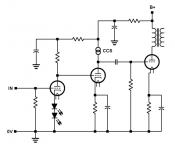
Something along these lines...
One could also rearrange it to DC-couple between the driver stage and output.
Attachments
Last edited:
My various tube manuals have a different set of operating conditions from above and I couldn't find any reference at all to max Ip only max plate voltage which is given as 300V.
Typical operation:
Ep= 250V Eg= -2V mu= 100 rp= 66k, gm = 1500 umhos Ip= .9mA
Ep= 100V Eg= -1V mu= 100 rp= 85k, gm = 1500 umhos Ip= .4mA
My bad, I found a single line description on a website and Ctrl+C, Ctrl+V. Should have consulted the tube manual.
The 6SF5 description I found mentioned that it was designed for use with battery operated receivers, hence the really low current operation. What you show is more akin to a 12AX7.
So if the 6SF5 is set to draw 0.8mA, it could drive the 2A3 grid up to above 20kHz without slewing... Correct?
--
In my tests running that tube CCS loaded at much over 5 ma creates a slew of complex higher harmonic distortion components. Pushing the dissipation limits made it unusable.
You just need to set it up with a lot of care. I use a plate stopper, dual grid stoppers, and 4 cathode stoppers, all SMD, and all right on the pins. I also use teflon sockets. I run mine at ~18mA and they work great -- smooth and warm
")
Would a cascade of common cathode 5687 to 5687 with CCS plate loads sound or measure worse?
--
Something along these lines...
One could also rearrange it to DC-couple between the driver stage and output.
Glad I asked. That's a two stage input/driver, consisting of grounded cathode amplifiers in series. It's different in several ways from the amp I suggested:
One input voltage gain stage/ two voltage gain stages.
Non-inverting/ inverting.
Un-bypassed/bypassed cathodes.
PS noise canceling/conventional.
Direct coupled/ cap coupled (or cap placed after input tube).
0.9V sensitivity/0.3V sensitivity
In other words, a completely different amp. Better or worse sound or measurements? Depends on taste and operating points.
If I were making it, I would rearrange it and leave some room to drive it into A2 operation. Actually if you are going this far, I'd add a negative supply, use a higher mu tube on the front end, followed by a source follower.
Sheldon
You just need to set it up with a lot of care. I use a plate stopper, dual grid stoppers, and 4 cathode stoppers, all SMD, and all right on the pins. I also use teflon sockets. I run mine at ~18mA and they work great -- smooth and warm
Hi, do you take such heavy precautions with all high transconductance VHF tubes or is 6s45pi really exceptional? I have only ever used cathode stoppers on cathode followers-I did not know it was ever necessary.
Member
Joined 2009
Paid Member
Have not double checked values, but should be close. Rod's or Tentlabs DC 2.5V filament supply a good option.
It would be interesting to hear the difference if the grid of the 2A3 were driven not from the CF but from the plate of the input tube. The 2nd triode would be used solely to provide the boosted anode and not drive the output tube. Yeah I know it seems stupid but 'people' say a CF doesn't always sound 'right'.
'Wimpy' driver mentioned in the start sound good perhaps b/c:
5. They probably found the amp to sound nice as is, why fix it? My guess.
Anyhow, the conclusion is that wimpy drivers can work just fine. But why they sound so good is not clear. It is possible that the lower h.f. roll off is actually more pleasing for some listeners. I'm not convinced. But it turns out that for many who have offered an opinion, the Fi 2A3 sounds better than the alternatives. Some people say it is the BEST sounding 2A3 they've heard. Is the harmonic profile of a resistor loaded high-mu tube something special ?
Last edited:
Hi, do you take such heavy precautions with all high transconductance VHF tubes or is 6s45pi really exceptional? I have only ever used cathode stoppers on cathode followers-I did not know it was ever necessary.
Depends on the tube, I suppose, but 6c45, 7788, etc. all seem to need the stoppers. D3a, C3g, etc. are a little easier to work with, which makes sense as the gm is a little lower.
It would be interesting to hear the difference if the grid of the 2A3 were driven not from the CF but from the plate of the input tube. The 2nd triode would be used solely to provide the boosted anode and not drive the output tube. Yeah I know it seems stupid but 'people' say a CF doesn't always sound 'right'.
It probably doesn't sound right, because it isn't used right. Just because they offer low output impedance, doesn't mean they like too much of a load (see Sy's many posts on this). In this application, the load is very light.
If you are suspicious of cathode followers, then a source follower will work fine and drive almost anything. Or, you could use a cascoded current source for the plate load, and take your signal from the u-follower output. A DN2540 for both, or the DN on top and your choice of jfet for the bottom.
Or try all three methods and see what you like. Only a few component changes needed. You need to save room for two extra triode sections, but you can use one from each tube, if they have the same base. BTW, an AX7 or AT7 would work in either position. Don't need to go octal (though more sexy looking).
Sheldon
- Status
- This old topic is closed. If you want to reopen this topic, contact a moderator using the "Report Post" button.
- Home
- Amplifiers
- Tubes / Valves
- why do wimpy drivers for 2A3 work as well as they do?